7-Segments-Board for Embedded Systems

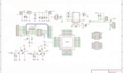
Design and Implementation of 7-Segments-Board 1.0 – An Extension Module for Embedded System Prototype Introduction When developing embedded systems, it would be helpful if we could have a module for monitoring purposes. For instance, let say that your system has to process data streams. In the testing and verification step, we need to compare each input and output bytes to verify that your system is doing right. Having a monitor module is surely a great help for engineers. Some development board has monitor module integrated, such as Altera UP1X FPGA Development Board. Inspired by its usage and benefit of such a monitor, 7-Segments-Board 1.0 is designed as an extension module for embedded system prototypes. Description 7-Segments-Board 1.0 is a low-cost, low-power MCU extension module for monitoring purposes. It aims to help engineers doing the firmware testing and debugging on hardware prototypes. For those who build microcontroller prototype devices from scratch and do not have access to sophisticated debugging instruments, using this module would make the testing and verification process less painful. 7-Segments-Board 1.0 is designed for an 8-bit microcontroller system. Module Specifications The module specifications are as follows: Input: General purpose push-button (PB) switches (dry contact). Output: Seven-segments LED to…

Continue reading

Z axis accelerometer MMA1220D from Freescale

MMA1220D is Z-axis MEMS accelerometer -8g – +8g. This sensor has a capacitive sensor. The output signal is passed through a 4 poles low pass filter. It also has an internal self-test capability. The main features:Integral signal conditioning;Linear output;Ratiometric performance;4th order Bessel Filter to preserve pulse shape integrity;Calibrated self-test;Detection of low voltage also clock monitor and EPROM Parity check status;Can survive big shocks. Where can it be used? It can be the perfect tool for Vibration monitoring, control, bearing monitor, PC HDD protection, mouse and joystick, virtual reality, sports diagnostics.The datasheet can be found here:https://www.freescale.comI decided to run a sample test for this sensor. For this, I just made a simple board where I soldered this sensor with the SOIC16 package. According to the datasheet, I put an RC filter on sensor output to minimize clock noise. There is a schematic: And traced PCB: I used SMD parts as it will be easier to glue another side of the board to any surface in the future. First test drive on oscilloscope: Later I will do some tests by connecting this sensor to MCU.Bellow, I attached the Protel library of the MMA1220D sensor and my project files. It might be you…

Continue reading

PCB Etcher

After UV-80 was built, there was a thought about automatic PCB Etcher with autonomous Heater and bubble machine. This project is hanging in the prefinished phase, but it does a job. It was used to etch several PCBs. As this etcher is supposed to be used for making PCBs using photosensitive technology, the controller is supposed to control both = the heater of the etching tank and the developer’s heater. As Sensors, there are used AD7416 digital temperature sensors. I decided to publish this small project, as this is not clear when it will be finished. When it is, I will update this article. There is a little dirty drawing with dimensions: The dimensions are as follows 215x275x30 exterior. The inner volume is smaller as glass is 4mm thick. So the overall volume is less than 1,2 liter. It is an ideal volume to use one bag of ammonium persulphate or 250 grams of FeCl3. The glass plates are glued with aqua silicone. Sides are strengthened with aluminum profiles (not necessary if you have skills of glueing aquariums).

Continue reading

Ultraviolet light source UV-80 for PCB exposure

One of the more advanced PCB manufacturing methods is exposing laminate copper boards covered by a photo resistive layer through the mask. Using UV light in manufacturing PCB’s has many benefits according to other methods: you can get thin tracks like 0.2mm. You couldn’t do this using other home techniques like laser printers or hand artwork; another advantage is that this method gives a clean image – smooth edges of PCB tracks. Little bit effort and you can compare results to commercial products. And of course, the third benefit is speed and multiple replications of your boards by using the same mask. This article is described in the manufacturing of an automatic ultraviolet light source exposure box. Parts for UV box Case with organic glassPanelUV lamps ballasts and startersController Case Case is made of 5mm wood board wired with screws. Making a control panel The Control panel consists of two parts: Power control and Automatic control.A POWER switch is used to turn the on/off the power of the UV box. Green LED indicates the ON. MANUAL/AUTOMATIC switch is used to power l the UV lamps manually or automatically. Switches UPSIDE and UNDERSIDE are used to enable upper and lower lamps…

Continue reading

Imaging system with four different wavelengths obtained from LEDs

To evaluate skin pigmentation in different skin layers, a special light adapter is needed to take multispectral pictures of the skin. As there are different optical properties of skin pigments, four different light sources have been chosen. blue λ= 470 nm – highly absorbed by epidermal melanin green λ= 576 nm – hemoglobin peak red  λ= 660nm – epidermal-dermal boundary IR λ= 865 nm – low absorption, sensitive to scattering to measure papillary dermis thickness. There was a lighting source for the “Nikon Coolpix E3100” digital camera developed to take multispectral images of skin. Making an adapter The drawing of  lighting adapter The lightning adapter isn’t tough to build. It would help if you made a circular PCB and solder LEDs with protective resistors. The PCB image:

Continue reading

Interfacing MPXV5100 pressure sensor to Atmega8

The MPX5100 series piezoresistive transducer is a state-of-the-art monolithic silicon pressure sensor designed for many applications. Still, particularly it is convenient to interface to a microcontroller or microprocessor with ADC inputs. This is thin-film metallization and bipolar processing to provide an accurate, high-level analogue output signal proportional to the applied pressure. More details can be found here MPXV5100 This sensor measures differential pressure comparing to atmospheric so when there is no pressure applied it shows 0kPa;

Continue reading

Analog Devices Digital temperature sensor AD7416

There are many situations when you might need to measure temperatures or trigger some events due to temperature changes. It is very convenient to have these values in a digital format. Then you can transfer digital values to the microcontroller to process data or just to display on the LCD screen. AD7416 Sensor description This is a 10-bit digital temperature sensor that can measure temperatures in the range interval -40 to 125ï‚°C). Temperature conversion ADC has 15 conversion times. The sensor can be supplied from 2.7 to 5.5V, so it is no problem to connect directly to ARM microcontrollers. Data is transferred through the I2C serial interface. The more detailed description and datasheet can be downloaded from Analog devices page: AD7416. Here you find a simple routine where the Atmega8 microcontroller reads sensor data decodes temperature value and displays it on a 2×16 LCD display.

Continue reading

AVR ISP

AVRISP is a very popular Parallel port programmer for flashing AVR type microcontrollers. Earlier I used programmer connected to com port, but frequently I needed this port for other purposes; I decided to make it work on the parallel port. The programmer on a parallel port is much simpler than connected to a serial port because there is no needed voltage adapter like MAX232. You can only connect your MCU directly to the port. But for safety reasons, there is good practice to use buffer ships like 74HC244. The header for programmer I used standard 6 pin ISP header.

Continue reading

ARM7-Base development board for LPC2148

After the ARM mini-board for LPC2148 is created, it’s time to develop a development board. I want to make the board as universal as possible.So I decided to put I2C, SPI, COM, and JTAG on board. I decided to use an external voltage adapter as there are needed 5V and 3.3V DC sources. For my experiments, I can use those voltages straight from a PC source. 5V there is used to supply MAX232IC. I decided to use it instead of MAX3232 because it is easier to get them in the market. Of course, I left the ability to use and MAX3232 by changing the jumper. All other free pins I made accessible by adding pinheads inboard.

Continue reading

ARM7 LPC2148 mini board

One day I’ve got an ARM LPC2148 chip in my hands. The Philips LPC2148 is an ARM7TDMI-S based high-performance 32-bit RISC Microcontroller with Thumb extensions 512KB on-chip Flash ROM with In-System Programming (ISP) and In-Application Programming (IAP), 32KB RAM, Vectored Interrupt Controller, Two 10bit ADCs with 14 channels, USB 2.0 Full Speed Device Controller, Two UARTs, one with full modem interface. Two I2C serial interfaces, Two SPI serial interfaces, Two 32-bit timers, Watchdog Timer, a PWM unit, Real-Time Clock with optional battery backup, Brown-out detect circuit General purpose I/O pins. CPU clock up to 60 MHz, On-chip crystal oscillator, and On-chip PLL.

Continue reading