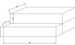
One of the more advanced PCB manufacturing methods is exposing laminate copper boards covered by a photo resistive layer through the mask. Using UV light in manufacturing PCB’s has many benefits according to other methods: you can get thin tracks like 0.2mm. You couldn’t do this using other home techniques like laser printers or hand artwork; another advantage is that this method gives a clean image – smooth edges of PCB tracks. Little bit effort and you can compare results to commercial products. And of course, the third benefit is speed and multiple replications of your boards by using the same mask. This article is described in the manufacturing of an automatic ultraviolet light source exposure box. Parts for UV box Case with organic glassPanelUV lamps ballasts and startersController Case Case is made of 5mm wood board wired with screws. Making a control panel The Control panel consists of two parts: Power control and Automatic control.A POWER switch is used to turn the on/off the power of the UV box. Green LED indicates the ON. MANUAL/AUTOMATIC switch is used to power l the UV lamps manually or automatically. Switches UPSIDE and UNDERSIDE are used to enable upper and lower lamps…
Continue reading