Electret condenser microphone amplifier for use in microcontroller projects

electret microphone

Most microcontrollers have ADC input, which can sample an analog signal, including sound. Even using Arduino, you can do many cool projects using audio information. For instance, you can make a voice-controlled device such as Audio Recorder, voice-activated switch, and more exciting audio-related projects. In this post, I want to focus a bit on the microphone part – the circuit required between the electret condenser microphone and MCU ADC input. Generally speaking, you cannot connect the electret microphone directly to the ADC pin and expect it to work. The part needed here is called an electret condenser microphone amplifier circuit. Electret microphone with preamplifier stage Condenser microphones require power from a battery or external source. The resulting audio signal is a stronger signal comparing to a dynamic microphone. First of all, the electret microphone isn’t only a condenser inside. It already has a preamplifier inside usually made of FET transistor, which is connected in common source configuration: First, the electret microphone needs to be powered through the drain pull-up resistor. Its value depends on the power supply voltage. The rule of thumb is to add 1kΩ per +1V of the power supply. Up to 10V 10kΩ resistor will work fine.

Continue reading

Experiment with Joule thief circuit

joule thief

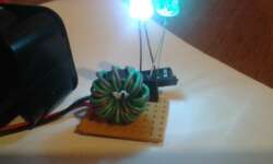
Joule thief circuit is popular among electronics enthusiasts. It has many implementations but probably the most common is a very minimalist voltage booster based on NPN transistor, coil, resistor, and LED. Its primary intent is to squeeze the remaining juice of dying batteries to light a LED. Since a pile of dying batteries keeps growing, I decided to give it a try. Instead of building the real circuit blindly, I decided to understand what is going on inside the circuit. So I made this circuit on the LTSpice simulator. You may find some difficulties when adding a transformer to the circuit, there is an excellent video on how to do this.

Continue reading

Simulating MOSFET based bidirectional 3.3V to 5V logic level shifter

clamping diode

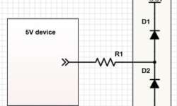
Different logic levels are a common problem in various circuits. For instance, Arduino boards come powered from 5V or 3.3V. Raspberry Pi is powered at 3.3V, and it accepts and generates 3.3V signals on its GPIO. This is fine until you need to connect the 5V peripheral to a 3.3V device. This can be a simple LCD. Of course, you can get 3.3V LCDs, but this is not always the solution. Sometimes it is handy to build a voltage level converter. It can be a special buffer IC like SN74LVCC3245A. These work great as bidirectional voltage translators. But in many cases, there is no need for another IC in your circuit. Hobbyists like to go with simpler solutions. The simplest way is to use resistors, where signal levels differ. The fact is that in most cases, devices have clamping diodes on the inputs that are meant to protect a further circuit from over-voltages. For instance, clamping diode inside a 3.3v device will try to limit the input voltage to 3.3V. This is why a series resistor necessary to limit the current flowing through the diode. Using resistors doesn’t guarantee safe operation. First of all, you must be sure that the…

Continue reading

Transistor based class AB amplifier

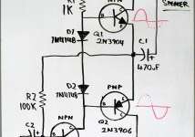
In most small audio projects, hobbyists are using specialized audio amplifier chips. That’s really fine; you get high-quality amplification without scratching your head. Some probably don’t care how these things work. But don’t forget that amplifiers can be built out of discrete electronics components like bipolar transistors. Check out this great hack week project where Dino makes a class AB audio amplifier out of three bipolar transistors and other passive components. He slightly goes through the theory of operation and, of course, demonstrates its working in the following video.

Continue reading

The Multipurpose Controllable Power Outlet

For all the home hobbyists, you knew that dealing with microcontrollers is a fun thing. Once you have been hooked with it, there was no turning back. Do you know that a microcontroller’s GPIO (General-purpose input/output) pins cannot handle higher power requirements? An LED was easy enough, but how about the large power items such as light bulbs, toaster ovens or blenders that required more circuitry? In this case, a relay is wanted in this situation. However, building a 5V controllable power outlet can be handy for many applications; thus a relay is a perfect choice for this project! For your information, a relay is a large mechanical switch, where the switch is toggled on or off by energizing a coil constantly. By applying the relay in the project, it will ensure your safety. Let’s take an example. If you have 120VAC running through the paddles, you don’t have to worry that 120VAC will sneak back into and vaporise your microcontroller connected to the coil, as the paddles are capable of carrying substantial currents! Furthermore, you can use the relay to control a DC motor or an AC lamp if you want to.

Continue reading

Show Your Talent by DIY a Sun Tracking Unit

Probably you saw the Sun tracking system before; however, do you have the urge to challenge yourself to make a Sun Tracking Unit? First of all, get a tiny .7″x1.4″ PC board using the LED3X sensor concept. This circuit uses power MOSFET drivers, which most any DC motor can be used without any modification. You might notice that the power drivers are good enough for delivering about 50 amps of peak current or even more. The current will increase accordingly to the transistor. This means the large power MOSFET, 72A, when operated in low power mode, will eliminate the transistor’s need for a heat sink. Cool, isn’t it?

Continue reading

DIY pulse soldering iron

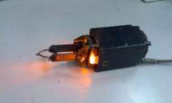
The biggest benefit I see when working with a pulse soldering iron is speed and effectiveness. Of course, when you don’t work, it stays cool; this means it saves energy, doesn’t evaporate poisonous steam, and there is no risk of accidentally burning yourself. Well, this one even has a light source for a better view when soldering. If you like to hack things, you may try this challenge on building a pulse soldering iron. This iron may be powered from a 220V supply and consumes about 70-100W of power. Efficiency reaches about 50%. The heating time takes 5 seconds while cooling to 50ºC takes about 15 seconds. Soldering iron may be used in various tasks, including repairing home appliances, replacing electronic parts, etc.

Continue reading