Tip on storing initial values in EEPROM of AVR microcontroller
AVR microcontrollers have EEPROM memory built-in, which adds a lot of abilities to store constant values, calibration data, and other data that may be read and changed at any time during program flow. I have used EEPROM for storing the last device configuration on a couple of projects, e.g., in TDA7313 volume, BASS, TREBLE input, and output channel information is updated each time when it has been changed. After the device is turned ON, it reads the last saved settings from EEPROM memory and restores the last device state. But what happens when you turn the device for the first time. It has to read initial values that have to be stored or read ‘FF,’ which may lead to a crash or something else. One way is to prepare a separate *.eep file with initial EEPROM data and then burn it separately to microcontrollers EEPROM. But this may not always be handy. So this is a simple trick to store initial values to EEPROM at the first microcontroller run and skip this part later without additional files needing to be flashed in. Probably others are doing a bit. Differently, this is how I do. After main() I add following code:…

Continue reading

Building and installing USBASP-USB programmer of AVR microcontrollers

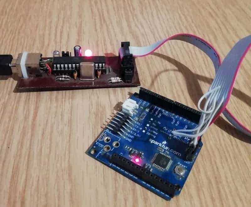
USBASP is a well-known USB programmer for Atmel AVR microcontrollers initially supported by  Thomas Fischl. USBasp flash uploader is made of an Atmega8 or Atmega88 and few other components, including resistors, capacitors, LEDs, and connectors. The adapter works on a firmware driver, which gives room for customization, and new chips updates. The USBasp programmer has been so famous for a long time. It has been supported by avrdude – an open-source programming software, which runs on multiple platforms like Windows, Linux, or Mac. Since Arduino’s popularity has skyrocketed, the need for such tools has diminished, and so the support has been stopped. I can assure you that USBasp still works and there is no problem running it on Windows 10. USBasp circuit diagram Let us see what is this adapter is made of and how to set it up to run on Windows 10. You can find the original circuit on the author’s site: http://www.fischl.de/usbasp/. There you will also find several third-party PCB examples to choose from. The USBasp adapter is an Atmega8 (or Atmega88) microcontroller clocked with a 12MHz crystal. The assembled PCB is ready to be connected via a simple USB B-type cable (PC side needs A type…

Continue reading

Interfacing rotary encoder to AVR microcontroller

Recently I was working on a project where I used a rotary encoder. I could share some thoughts on how the rotary encoder should be interfaced to AVR MCU and write a code to read its value. It is relatively easy to connect and program rotary encoders – only three wires are required to connect to the microcontroller (two for signal quadrature outputs) and one for reference GND). When the encoder knob is turned in either direction, it generates a Grey code on the outputs, allowing tracking turn speed and direction. Rotary encoder allows including a convenient user interface option with a single knob. Many rotary encoders also come with an integrated button on the knob itself – so menu navigation becomes even more comfortable. In our example project, we are going to use a 12-step mechanical rotary encoder from SparkFun. It is interfaced to ATMega32 board with graphical LCD.

Continue reading

Control AVR 8 bit Timer-Counter0 using AVR-GCC

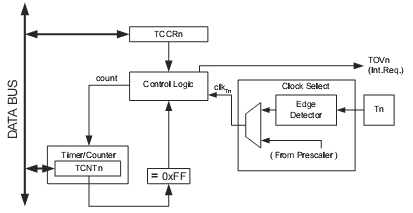
Timers are an essential part of embedded systems. They make your life much more comfortable if used properly. Timers run independently to the main program flow so that they can do the job individually without disturbing precious calculations done by the CPU. You just set up the timer and let it run while your main program performs other tasks. Timers are easy to set up. In this post, an example is made for Atmega8 timers. Other AVR microcontroller models and even different brand chips have similar timers. Atmega8 has two 8-bit timers/counters and one 16-bit timer counter with many abilities. Standard 8-bit Timer/Counter0 features are: TCNT0 is an 8-bit timer counter register that keeps the current count number. The timer counter can be clocked by an external clock through pin T0 or from internal via pre-scaler. The timer counter increments (MAX value is 0xFF) and then restarts from BOTTOM=0x00. After the timer Overflows, the flag TOV0 is written to 1, and if TOIE0 bit in SREG is set, then timer overflow interrupt is executed. TOV0 acts as a ninth bit of counter register that is only set but not cleared. When this bit is combined with timer overflow interrupt –…

Continue reading

Choosing right programmer for AVR microcontrollers

Once you start building something with microcontrollers, one thing you need to take into account is a programming adapter. This is a device that allows uploading compiled code into the chip. I don’t know if this is still fun to build your DIY programming adapter, which is not guaranteed to support all chips, nor will it be safe and reliable. AVR microcontroller niche is one of the most interesting when talking about programmers. If you look at the AVRDUDE configuration file, you will find that there are about 50 of them. Many of them are DIY, while others are official. When I started with microcontrollers, I also was looking for a cheap and easy to build programming adapter. So I have built several if a few years. The first of them was RS232 based programmer that worked with then-popular PonyProg software. Later followed LPT port programmer:

Continue reading

Using analog joystick in AVR projects

joystick

In many cases, the joystick manipulator is the best choice for user input. Whether it is a game, robot, or flying machine – a joystick is the most intuitive way of controlling them. You can actually find them in gaming controllers like PlayStation or XBOX. The one we are going to the interface is Thumb Joystick I purchased some time ago from SparkFun. They are really cheap, and as users report, it is practically the same as in XBOX 360, which can be replaced if one is broken. I didn’t bother making a PCB for it – I just used a breakout board for it, which also can be found on SparkFun. Simply speaking, this joystick is nothing more than two potentiometers and one pushbutton. It is designed so that potentiometers are oriented perpendicular and thus moving stick; you can have X and Y-axis control. The push-button is simply an action button that can be activated by pressing the joystick down. So controlling joystick is a matter of analog read of both potentiometers with microcontroller ADC inputs.

Continue reading

Interrupt driven AVR USART communication

avr usart

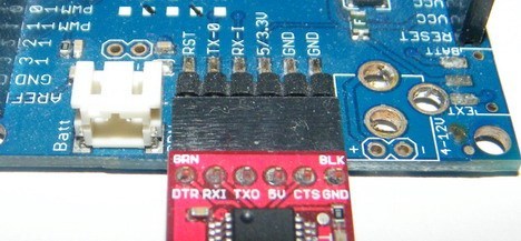
Simple USART routines are not always practical because waiting transmitting buffer to be ready in a simple loop occupies processor resources. If we do not know when data will be received, we are just wasting resources inside the waiting loop. Another issue arises when multiple data bytes have to be sent/received. In this case, we have to write complex code to deal with the data flow. Since the microcontroller’s specialty is interrupting, it is better to use them to handle communications, improving overall performance and energy saving. Instead of continuously checking if there new data received in the UDR register or checking if send buffer is free, lets us write a more effective USAR communication code with a guardian, which would wake the MCU if it has received a byte via USART. On the other hand, Interrupt mode allows performing other tasks at total capacity while waiting for USART interrupt. Let us implement interrupt driven AVR USART communication example.

Continue reading

AVR GCC LCD library allows connecting pins in any order

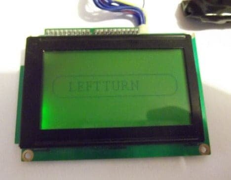
Probably some of you are struggling in finding a proper LCD driver that would work on any circuit. I just wanted to point out that I found some time to improve my current LCD library to support a mixed pin connection case. Earlier, you had to connect LCD in a pretty strict way where pins had to be aligned and attached to a single AVR port. Sometimes this can’t be done for various reasons – you want to use those pins for other alternative functions, or you want to trace your PCB better, etc. In this updated version of the library, there are two more modes added: LCD_4BIT_M and LCD_8BIT_M that allow controlling LCDs either in 4 or 8-bit mode but with any pin connection layout. So data pins and control pins can be connected to any PIN and any port. A couple of examples should give some clue on how to start using it. If you used this library for some project, you only need to modify the header file while the project source code can remain the same.

Continue reading

FreeRTOS on AVR with external RAM

AVR microcontrollers aren’t the best choice to run the FreeRTOS scheduler due to low on-chip RAM. Atmega128 has only 4K of RAM, so this limits the FreeRTOS functionality to very basic. This problem can be solved by adding extra RAM, which may be connected to an external memory interface. We have already built an external memory block of 8K previously to test it with FreeRTOS applications. Let’s continue with our previous code, which runs several simple tasks (button state reading, LCD output, and LED flash), and we can add more to it. We are going to set up an external RAM for storing heaps. This will allow the storage of large data buffers without worrying too much about heap and stack overlaps.

Continue reading

Running multiple FreeRTOS tasks on AVR

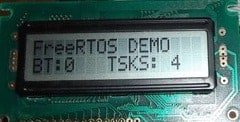
In the previous post, we just run a single task. Running RTOS with a single task has no meaning at all. This can be quickly done with a conventional program. But what if we need to have more separate functions. To execute them at exact timing would require a separate timer or interrupt. But microcontroller cannot guarantee an interruption for every task. This way, it is hard to make code modular, and testing can be painful. Using RTOS solves this kind of problem. It allows programming each task as an endless loop. Kernel scheduler takes care of assuring each task gets its chunk of processing time. Additionally, it does bearing the priority systems – more critical tasks are executed before less important ones. Let us go further with our example code and add more tasks to our FreeRTOS engine. We already have an LED flashing task that toggles LED every second. Additionally, we are going to create another task that checks the button state. Also, we are going to send some information to the LCD. As always, let’s take care of drivers for all of them.

Continue reading