
Probably some of you are struggling in finding a proper LCD driver that would work on any circuit. I just wanted to point out that I found some time to improve my current LCD library to support a mixed pin connection case. Earlier, you had to connect LCD in a pretty strict way where pins had to be aligned and attached to a single AVR port. Sometimes this can’t be done for various reasons – you want to use those pins for other alternative functions, or you want to trace your PCB better, etc.

In this updated version of the library, there are two more modes added: LCD_4BIT_M and LCD_8BIT_M that allow controlling LCDs either in 4 or 8-bit mode but with any pin connection layout. So data pins and control pins can be connected to any PIN and any port. A couple of examples should give some clue on how to start using it. If you used this library for some project, you only need to modify the header file while the project source code can remain the same.
Configuring LCD for 4-bit mixed pin mode
Let’s look at what you need to start using these features. We can do this by selecting a simple example. This time 4-bit mixed mode:
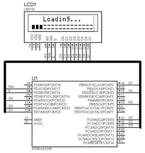
For instance, LCD pins are connected to Atmega328P in following way:
RS – > PB5
RW – > PD1
E – > PD2
D4 – > PD4
D5 – > PC2
D6 – > PD6
D7 – > PB0
So we get the unaligned situation. First of all, we need to edit pin assignments in lcd_lib.h. First of all, uncomment one of the following defines that indicate the mode chosen
//LCD 4-bit interface is used (single port pins)
//#define LCD_4BIT
//LCD 8-bit interface is used (single port pins)
//#define LCD_8BIT
//LCD 4-bit interface is used (mixed port pins)
#define LCD_4BIT_M
//LCD 8-bit interface is used (mixed port pins)
//#define LCD_8BIT_M
This time we use LCD_4BIT_M
Then we need to associate LCD pins with port PINs. If LCD_RS is connected to PB5 pin, then we write 5:
#define LCD_RS 5 //define MCU pin connected to LCD RS
#define LCD_RW 1 //define MCU pin connected to LCD R/W
#define LCD_E 2 //define MCU pin connected to LCD E
#define LCD_D0 0 //define MCU pin connected to LCD D0
#define LCD_D1 1 //define MCU pin connected to LCD D1
#define LCD_D2 2 //define MCU pin connected to LCD D2
#define LCD_D3 3 //define MCU pin connected to LCD D3
#define LCD_D4 4 //define MCU pin connected to LCD D4
#define LCD_D5 2 //define MCU pin connected to LCD D5
#define LCD_D6 6 //define MCU pin connected to LCD D6
#define LCD_D7 0 //define MCU pin connected to LCD D7
And now we have to define the port and data direction register for each pin. As pins may be connected to different ports – we need to work with individual pins. We edit this part:
#ifdef LCD_4BIT_M || LCD_8BIT_M //8- bit or 4 - bit mode
#define LDPRS PORTB //RS pin assignment
#define LDDRS DDRB
#define LDPRW PORTD //RW pin assignment
#define LDDRW DDRD
#define LDPE PORTD //E pin assignment
#define LDDE DDRD
#define LDPD0 PORTD //D0 pin assignment
#define LDDD0 DDRD
#define LDPD1 PORTD //D1 pin assignment
#define LDDD1 DDRD
#define LDPD2 PORTD //D2 pin assignment
#define LDDD2 DDRD
#define LDPD3 PORTD //D3 pin assignment
#define LDDD3 DDRD
#define LDPD4 PORTD //D4 pin assignment
#define LDDD4 DDRD
#define LDPD5 PORTC //D5 pin assignment
#define LDDD5 DDRC
#define LDPD6 PORTD //D6 pin assignment
#define LDDD6 DDRD
#define LDPD7 PORTB //D7 pin assignment
#define LDDD7 DDRB
#endif
This is practically it. We can start using LCD as we did in old library version.
Configuring LCD for 8-bit mixed pin mode
To make sure things are working correctly let’s set up a project for 8-bit mixed mode. To do so we connect LCD as follows:
Again we uncomment following mode:
#define LCD_8BIT_M
Then assign pin numbers:
#define LCD_RS 5 //define MCU pin connected to LCD RS
#define LCD_RW 1 //define MCU pin connected to LCD R/W
#define LCD_E 2 //define MCU pin connected to LCD E
#define LCD_D0 0 //define MCU pin connected to LCD D0
#define LCD_D1 7 //define MCU pin connected to LCD D1
#define LCD_D2 1 //define MCU pin connected to LCD D2
#define LCD_D3 2 //define MCU pin connected to LCD D3
#define LCD_D4 4 //define MCU pin connected to LCD D4
#define LCD_D5 2 //define MCU pin connected to LCD D5
#define LCD_D6 6 //define MCU pin connected to LCD D6
#define LCD_D7 0 //define MCU pin connected to LCD D7
and finally we chose ports for each pin assigned pin:
#if defined (LCD_4BIT_M) || defined (LCD_8BIT_M)
#define LDPRS PORTB //RS pin assignment
#define LDDRS DDRB
#define LDPRW PORTD //RW pin assignment
#define LDDRW DDRD
#define LDPE PORTD //E pin assignment
#define LDDE DDRD
#define LDPD0 PORTC //D0 pin assignment
#define LDDD0 DDRC
#define LDPD1 PORTD //D1 pin assignment
#define LDDD1 DDRD
#define LDPD2 PORTC //D2 pin assignment
#define LDDD2 DDRC
#define LDPD3 PORTB //D3 pin assignment
#define LDDD3 DDRB
#define LDPD4 PORTD //D4 pin assignment
#define LDDD4 DDRD
#define LDPD5 PORTC //D5 pin assignment
#define LDDD5 DDRC
#define LDPD6 PORTD //D6 pin assignment
#define LDDD6 DDRD
#define LDPD7 PORTB //D7 pin assignment
#define LDDD7 DDRB
#endif
Configuring LCD for normal 4-bit
In case you need to use LCD in a byte-aligned way like we used to do in the old version of the LCD library. To do so, we need to uncomment mode:
#define LCD_4BIT
We still need to define pin numbers for for control and data pins.
#define LCD_RS 0 //define MCU pin connected to LCD RS
#define LCD_RW 1 //define MCU pin connected to LCD R/W
#define LCD_E 2 //define MCU pin connected to LCD E
#define LCD_D0 0 //define MCU pin connected to LCD D0
#define LCD_D1 1 //define MCU pin connected to LCD D1
#define LCD_D2 2 //define MCU pin connected to LCD D2
#define LCD_D3 3 //define MCU pin connected to LCD D3
#define LCD_D4 4 //define MCU pin connected to LCD D4
#define LCD_D5 5 //define MCU pin connected to LCD D5
#define LCD_D6 6 //define MCU pin connected to LCD D6
#define LCD_D7 7 //define MCU pin connected to LCD D7
Then we only need to define data and control ports as follows:
#if defined (LCD_4BIT) || defined (LCD_8BIT) //if aligned mode
#define LDP PORTD //define MCU port connected to LCD data pins
#define LCP PORTD //define MCU port connected to LCD control pins
#define LDDR DDRD //define MCU direction register for port connected to LCD data pins
#define LCDR DDRD //define MCU direction register for port connected to LCD control pins

#endif
Setting normal 8-bit mode
It is obvious that in pin aligned mode, LCD update is faster as either 4-bit or 8-bit mode accepts data faster – byte or nibble operation. In mixed mode, each pin needs to be set separately. This increases the number of instructions used to transfer byte. For instance, in order to send a byte in LCD_8BIT_M mode, I used a helper function:
static void LCDMix_8Bit(uint8_t data)
{
if((data)&(0b10000000)) LDPD7 |=1<<LCD_D7;
else LDPD7 &=~(1<<LCD_D7);
if((data)&(0b01000000)) LDPD6 |=1<<LCD_D6;
else LDPD6 &=~(1<<LCD_D6);
if((data)&(0b00100000)) LDPD5 |=1<<LCD_D5;
else LDPD5&=~(1<<LCD_D5);
if((data)&(0b00010000)) LDPD4 |=1<<LCD_D4;
else LDPD4 &=~(1<<LCD_D4);
if((data)&(0b00001000)) LDPD3 |=1<<LCD_D3;
else LDPD3 &=~(1<<LCD_D3);
if((data)&(0b00000100)) LDPD2 |=1<<LCD_D2;
else LDPD2 &=~(1<<LCD_D2);
if((data)&(0b00000010)) LDPD1 |=1<<LCD_D1;
else LDPD1&=~(1<<LCD_D1);
if((data)&(0b00000001)) LDPD0 |=1<<LCD_D0;
else LDPD0 &=~(1<<LCD_D0);
}
Every bit in the data byte is tested, and then the corresponding port pin is set or reset. If your application indicates information that doesn’t have to be updated frequently any mode is fine. But if you use LCD for dynamic indication like animations or other ways need and a fast LCD up, you probably chose normal 8-bit mode or at least 4-bit. If you find errors or difficulties in using this lib, feel free to post a comment.
My customizable 4-bit LCD lib:
http://www.avrfreaks.net/index.php?module=Freaks%20Academy&func=viewItem&item_type=project&item_id=2218
پروژه الکترونیک ARM STM32 LPC AVR PIC اتوماسیون مانیتورینگ کنترل صنعتی