Recently I was working on a project where I used a rotary encoder. I could share some thoughts on how the rotary encoder should be interfaced to AVR MCU and write a code to read its value.
It is relatively easy to connect and program rotary encoders – only three wires are required to connect to the microcontroller (two for signal quadrature outputs) and one for reference GND). When the encoder knob is turned in either direction, it generates a Grey code on the outputs, allowing tracking turn speed and direction.
Rotary encoder allows including a convenient user interface option with a single knob. Many rotary encoders also come with an integrated button on the knob itself – so menu navigation becomes even more comfortable. In our example project, we are going to use a 12-step mechanical rotary encoder from SparkFun.

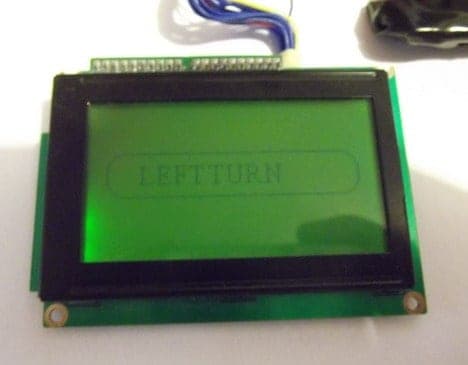
It is interfaced to ATMega32 board with graphical LCD.

You can find many projects on the internet where one of the rotary encoder pins is connected to a microcontroller interrupt pin. This enables easier detection of the first encoder turn. The endless main loop for tracking is not recommended because it occupies too many MCU resources for doing nothing.
Another logical solution is to use Timer, which periodically generates interrupts to check if the rotary encoder has been turned or the button has been pressed.
Let us use the timer option as it allows the connecting encoder to any available microcontroller pins. The rotary encoder in our schematic is connected to Atmega32 as follows:

- Encoder A pin to atmega32 pin B2
- Encoder pin B to MCU pin B3
- Button to pin B4
We are going to use atemga32 internal pull-ups on these pins. Let us write a simple code library for reading the rotary encoder. This will make code reusable and modular. First, we create two empty files rotary.c and rotary.h. In rotary.h we define AVR port pins and library function prototypes:
 #ifndef ROTARY_H
 #define ROTARY_H

 #include <avr/io.h>

 //define port where encoder is connected
 #define ROTPORT PORTB
 #define ROTDDR DDRB
 #define ROTPIN PINB
 //define rotary encoder pins
 #define ROTPA PB2
 #define ROTPB PB3
 #define ROTPBUTTON PB4
 //define macros to check status
 #define ROTA !((1<<ROTPA)&ROTPIN)
 #define ROTB !((1<<ROTPB)&ROTPIN)
 #define ROTCLICK !((1<<ROTPBUTTON)&ROTPIN)
 //prototypes
 void RotaryInit(void);
 void RotaryCheckStatus(void);
 uint8_t RotaryGetStatus(void);
 void RotaryResetStatus(void);
 #endif
In the library source file, we declare the following functions. First, initialize pins where rotary encoder is connected:
 void RotaryInit(void)
 {
 //set pins as input
 ROTDDR &= ~((1<<ROTPA)|(1<<ROTPB)|(1<<ROTPBUTTON));
 //enable interrnal pullups;
 ROTPORT |= (1<<ROTPA)|(1<<ROTPB)|(1<<ROTPBUTTON);
 }
Then we set selected port pins as inputs and enable internal pull-up resistors.
Let us write an encoder check status function that sets an internal variable to some variable.
void RotaryCheckStatus(void)
 {
 //reading rotary and button
 //check if rotation is left
             if(ROTA & (!ROTB)){
                         loop_until_bit_is_set(ROTPIN, ROTPA);
                         if (ROTB)
                                     rotarystatus=1;
                         //check if rotation is right
                         }else if(ROTB & (!ROTA)){
                                     loop_until_bit_is_set(ROTPIN, ROTPB);
                                     if (ROTA)
                                                 rotarystatus=2;
                         }else if (ROTA & ROTB){
                                     loop_until_bit_is_set(ROTPIN, ROTPA);
                                     if (ROTB)
                                                 rotarystatus=1;
                                     else rotarystatus=2;
                         }
             //check button status
             if (ROTCLICK)
                         {
                                     rotarystatus=3;
                         }
 }
- If the knob was turned left – rotary status is set to 1
- If right, then the value is 2
- If the button was pressed – the state is set to 3
The two following two returns status and resets it:
//return button status
 uint8_t RotaryGetStatus(void)
 {
 return rotarystatus;
 }
 //reset status
 void RotaryResetStatus(void)
 {
 rotarystatus=0;
 }
We are using a graphical LCD based on the ks0108 controller for displaying messages.
To check rotary encoder status, we are using Timer2 overflow interrupts. The microcontroller runs at 16MHz, so with
void Timer2_Start(void)
 {
             TCCR2|=(1<<CS22)|(1<<CS21); //prescaller 256 ~122 interrupts/s
             TIMSK|=(1<<TOIE2);//Enable Timer0 Overflow interrupts
 }
After the timer has been started, we can put the RotarryCheckStatus function inside it and read encoder actions:
ISR(TIMER2_OVF_vect)
 {
 //reading rotary and button
 RotaryCheckStatus();
 }