Using analog joystick in AVR projects

joystick

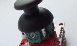
In many cases, the joystick manipulator is the best choice for user input. Whether it is a game, robot, or flying machine – a joystick is the most intuitive way of controlling them. You can actually find them in gaming controllers like PlayStation or XBOX. The one we are going to the interface is Thumb Joystick I purchased some time ago from SparkFun. They are really cheap, and as users report, it is practically the same as in XBOX 360, which can be replaced if one is broken. I didn’t bother making a PCB for it – I just used a breakout board for it, which also can be found on SparkFun. Simply speaking, this joystick is nothing more than two potentiometers and one pushbutton. It is designed so that potentiometers are oriented perpendicular and thus moving stick; you can have X and Y-axis control. The push-button is simply an action button that can be activated by pressing the joystick down. So controlling joystick is a matter of analog read of both potentiometers with microcontroller ADC inputs.

Continue reading

Using FreeRTOS kernel in AVR projects

FreeRTOS is known as Real-Time Operating System. It would probably be too dare to call it real-time-os, preferably a real-time scheduler where applications can be split into independent tasks that share complete processor resources by switching them rapidly. It. It looks like all functions are executed in parallel. This feature is called multitasking. There are many debates on using RTOS on AVR microcontrollers as they are arguably too small for the running scheduler. The main limitation is a small amount of ram and increased power usage. If you use lots of tasks in the application, you will probably run out of RAM to save context when switching between tasks. Consider FreeRTOS only if you use larger scale AVRs like Atmega128 or Atmega256. Indeed you can find smaller schedulers that are specially designed for smaller microcontrollers, even tiny series. On the other hand, if you master FreeRTOS, it can be used with multiple microcontrollers like ARM Cortex, PIC, and various compilers, including IAR, GCC, and Keil Rowley, Attolic. And the main reason to keep an eye on it – it is free. Probably it would take lots of time and space to go through RTOS theory. Some great information can be…

Continue reading

AVR DDS signal generator V2.0

Finally, the second version of the improved AVR DDS signal generator is here. THE first AVR DDS V1.0 generator was only an attempt to run the DDS algorithm without any analog amplitude control. In this DDS generator version, I still wanted to keep things as simple as possible using a minimum count of widely available components in the updated circuit. Also, I kept a single-sided PCB approach. AVR DDS specification AVR DDS signal generator V2.0 is a firmware-based DDS signal generator that uses a slightly modified Jesper’s mini DDS algorithm adapted to AVR-GCC C code as in-line ASM. The AVR DDS signal generator has two outputs – one for DDS signal and another for high speed [1, 8MHz] square signal – which may be used to bring back to life microcontrollers with wrong fuse settings for other purposes where a high-speed square signal may be needed. A high-speed (HS) signal is output directly from the Atmega16 OC1A(PD5) pin. The DDS output is used for all complex signals generated via the R2R resistor network and is adjusted via LM358N offset and amplitude regulating circuits. Two potentiometers can control offset and amplitude. The offset can be controlled in range +5V..-5V while magnitude…

Continue reading

DIY AVR Graphical LCD test board

Once I’ve got several HQM1286404 graphical LCDs around, I decided to build a prototyping board where I could easily plug LCD to it, read data via ADC and display graphs, and plug keypad if needed for some menu functions. Earlier, I tested graphical LCD on prototype breadboard but dealing with multiple wires (GLCD needs 20) resulted in many failures. It is OK to do simple tasks, but more complex applications require a more stable platform. So here it is: This type of GLCD is a standard 128×64 pixel matrix controlled by the KS0108 LCD controller. I have a smaller non-common pin-header where pins have 2mm step, so I had to draw it for Eagle library, which you will find in project files. I decided to make a simple circuit so it could fit in 100x50mm single-sided PCB. As base MCU, I used Atmega16, which can be replaced with Atmega32, which is pin-compatible with Atmega16 have more data memory.

Continue reading

Interfacing MPXV5100 pressure sensor to Atmega8

The MPX5100 series piezoresistive transducer is a state-of-the-art monolithic silicon pressure sensor designed for many applications. Still, particularly it is convenient to interface to a microcontroller or microprocessor with ADC inputs. This is thin-film metallization and bipolar processing to provide an accurate, high-level analogue output signal proportional to the applied pressure. More details can be found here MPXV5100 This sensor measures differential pressure comparing to atmospheric so when there is no pressure applied it shows 0kPa;

Continue reading

Analog Devices Digital temperature sensor AD7416

There are many situations when you might need to measure temperatures or trigger some events due to temperature changes. It is very convenient to have these values in a digital format. Then you can transfer digital values to the microcontroller to process data or just to display on the LCD screen. AD7416 Sensor description This is a 10-bit digital temperature sensor that can measure temperatures in the range interval -40 to 125ï‚°C). Temperature conversion ADC has 15 conversion times. The sensor can be supplied from 2.7 to 5.5V, so it is no problem to connect directly to ARM microcontrollers. Data is transferred through the I2C serial interface. The more detailed description and datasheet can be downloaded from Analog devices page: AD7416. Here you find a simple routine where the Atmega8 microcontroller reads sensor data decodes temperature value and displays it on a 2×16 LCD display.

Continue reading