AVR internal oscillator jitter research

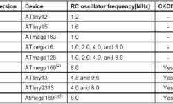
If you go to the AVR site and open an AVR application note AVR053, you will notice different RC oscillators installed into AVR chips during history. In the table, you can see tunable oscillator versions and their features. Simply speaking, each new version of the oscillator introduces better features and improvements. But is it true? ChaN has done exciting research on this oscillator version. He tested the output signal with fixed width and measured timing fluctuations of it. And he found out that the RC generator frequency slowly fluctuates during the time. Of course, RC oscillator fluctuations are not a problem as this type of clock source isn’t stable. In time-critical applications, it is better to use crystals. But the most exciting thing is that newer versions of tunable oscillators were generating much more jitter than older ones.

Continue reading

One click project with USBasp programmer

UASBASP is an efficient programmer for Atmel AVR microcontrollers that works under multiple operating systems, including Linux, Mac OS X, and windows. How to assemble this simple programmer read the previous article on this site or go to the original website of Thomas Fischl. As it was mentioned, USBasp has two available programming frequencies – high when the jumper disconnected and low when connected. These frequencies are 375kHz and 8kHz. To use 375kHz speed, target MCU’s clock frequency must be at least 1.5MHz – four times higher than SCK. If the target is clocked with a low-speed oscillator like 32kHz, then the jumper has to be connected as it gives 8kHz SCK, which is also 4*8kHz=32kHz. Building and preparing this programmer should not be a problem as it uses very few components. If you use 6 PIN ISP programming header, then you need a 10 to 6 adapter — Flash Atmega8 with the newest firmware found on the authors’ site. Right now latest firmware is 2007-10-23. For other details, read in the readme file.

Continue reading

DIY AVR Graphical LCD test board

Once I’ve got several HQM1286404 graphical LCDs around, I decided to build a prototyping board where I could easily plug LCD to it, read data via ADC and display graphs, and plug keypad if needed for some menu functions. Earlier, I tested graphical LCD on prototype breadboard but dealing with multiple wires (GLCD needs 20) resulted in many failures. It is OK to do simple tasks, but more complex applications require a more stable platform. So here it is: This type of GLCD is a standard 128×64 pixel matrix controlled by the KS0108 LCD controller. I have a smaller non-common pin-header where pins have 2mm step, so I had to draw it for Eagle library, which you will find in project files. I decided to make a simple circuit so it could fit in 100x50mm single-sided PCB. As base MCU, I used Atmega16, which can be replaced with Atmega32, which is pin-compatible with Atmega16 have more data memory.

Continue reading

Simple signal drawing on graphical LCD routines

During my spare time, I have been playing with graphical LCD. This time I decided to display simple signals that are stored in microcontroller memory. The idea was to read signal values from a lookup table and display waveform on Graphical LCD. To make things more interesting, I divided the LCD screen into four smaller screens to activate them separately and draw signals in them. Graphical LCD is the same old HQM1286404 with KS0108 controller. I have used  Proteus simulator 128×64 graphical LCD(LGM12641BS1R), which is based on KS0108. How to implement and connect LCD there was a blog post (Simulate KS0108 graphical LCD with Proteus simulator )about it. I am just going to show main program routine. As I mentioned I have split 128×64 in to four smaller screens like this: So I get four smaller 32×63 screens where I can put different information. To do this, you can think of many ways of implementation. I have chosen a simple solution. I have created a simple structure that holds a currently active window position and size:

Continue reading

Testing AVR universal bootloader on Atmega128

After the project source code is developed, there is always a need to flash it to the microcontroller. There are a few ways to program AVR microcontrollers. Usually, we used to flash AVR’s with an ISP adapter (or another programmer) that is not always handy, especially when designing a device for the end-user who doesn’t have an ISP adapter or doesn’t know much about flashing MCU. So it is better to flash a bootloader program AVR MCU once with a programming adapter and later load firmware interactively when starting AVR. The bootloader allows updating the firmware without a programmer and enables different programs for different purposes depending on the situation flexibly. But enough about this. So my purpose today is to test AVR universal bootloader, which Shaoziyang is developing. He aimed to create a universal bootloader that works on different AVR microcontrollers with minimal code modifications. Bootloaders you can find on the Internet are mostly available for particular microcontrollers, and nobody wants to do a lot of modifications to adapt to different MCU when needed. This AVR universal bootloader can support most AVR microcontrollers (Mega series), which have the self-programmable capability, boot section, and UART. If the device has many…

Continue reading

AVR reads button state and indicates on LED

This is a simple demo program of reading button state, lighting LEDs, sending information via USART. 8 buttons are connected to Atmega16 port A, 8 LEDs to port B via current limiting resistors. While none of the buttons aren’t pressed, there is a running light on LEDs performed, but when any of the buttons are pressed, LEDs display the current 8 bit counter value in binary format. The same value is sent via USART – you can see a number in the terminal is connected. The program is very simple:

Continue reading

AVR based TDA7313 Audio processor control

TDA7313 audio processor has been used for more than ten years because of its simplicity, functionality, and proper parameters like low distortion and low noise. Chip is based on BIPOLAR/CMOS technology and can be used in various applications, including car radios, Hi-FI, simple mixers. TDA7313 chip has three external stereo inputs that allow multiplexing three incoming sound sources. It has a volume control with steps of 1.25dB, Treble and BASS control, Loudness function. Each of the four outputs has a distinct control that allows balancing outputs. A chip can be controlled via an I2C (TWI) interface. Description of Audio processor This project’s idea was to construct an independent audio processor that can be embedded in any sound system with the ability to control settings with a simple button interface with a menu preview in LCD. The intent was to cover all audio-processor functionality within the LCD menu.

Continue reading

Simulate KS0108 graphical LCD with Proteus simulator

Today it is common practice to use various circuit and microcontroller simulators for developing programs. Using simulators, you have several benefits comparing to real prototype boards. You don’t have to connect any hardware to test a piece of code; also, you don’t have to be in the same place when working. You can have simulator software on your Laptop and work where ever you want. Of course, you can see more parameters within the simulator like register values, memory, signals in a convenient form. So controlling graphical LCD on simulator software like Proteus is an easy task.

Continue reading

Controlling graphical 128×64 LCD based on KS0108

HQM1286404 is a pretty old graphical LCD module, but it is still popular. KS0108 driver controls this LCD. LCD backlight color is yellow-green. I think this is an excellent choice for many projects where graphical information is needed for several reasons – you can find libraries around the internet to start working in just a few minutes. Several tools can also be used to generate character arrays and graphics. The hardest thing for me was to find the correct wiring as the datasheet I have was for the next PCB revision (HQM1286405) as mine are HQM1286404, so don’t be mistaken as I did. Here is the correct pin-out of LCD:

Continue reading