Build Piconomic Atmega128 development board by yourself

First of all, I have ordered to make PCB by using a milling-drilling plotter. Of course, I could make the board by myself, but I wanted to save some time and nerves in case of errors. After one week my board was shipped to me: Then I bought all parts needed. One thing that didn’t go well was that I couldn’t get capacitors and resistors in SMD packages 0603, so I used 0805 to lie on the side.

Continue reading

Generate sine wave modulated PWM with AVR microcontroller

This example will show how ease can sinewave modulated PWM modulated using an AVR microcontroller and a few code lines. For this example, I used Atmega8 MCU. All project is set up in VMLAB simulator. To achieve this, I saved a sinewave lookup table in a Program memory (don’t forget to include interrupt.h header file): PWM is generated by using Phase and frequency correct PWM using a 16-bit timer in Atmega8. Modulation is done by updating the OCR1A value with one from the sinewave table when comparing matches. Reading from flash program memory is done simply: The line above is placed inside the output compare interrupt for OCR1A service routine. Resulting signal in scope simulator: Download project Sinewave modulated PWM source code if you want to try it by yourself. This way, you can modulate PWM with any signal shape that is stored in the lookup table. Updated AVRStudio4 project files!

Continue reading

Two AVR-GCC examples of using AVR 8 bit Timers

Timers are an essential part of microcontrollers. They can be used in many areas starting with simple timed routines to RTOS. The good thing is that timers run independently of the main program flow. Set up the timer counter and let it do its job while your main program runs and does its job. Let’s take the AVR Atmega8 microcontroller. It has two independent 8-bit timers. One is a little simpler which is featured with essential functions like: Single-channel counter; Frequency generator; External Event counter; 10 – bit clock pre-scaler. Another is more advanced where is OCR (output compare register) included, which allows implementing PWM routines. It has the following features: Single Channel Counter Clear Timer on Compare Match (Auto Reload) Glitch-free, phase Correct Pulse Width Modulator (PWM) Frequency Generator 10-bit Clock Pre-scaler Overflow and Compare Match Interrupt Sources (TOV2 and OCF2) Allows Clocking from External 32 kHz Watch Crystal Independent of the I/O Clock Datasheet documents these timers pretty well. Let’s view a couple of examples with both 8-bit timers. The first example is to do a simple task – every time timer overflows, it has to increase the variable value. And this variable is sent to PORTB in…

Continue reading

Simple TTL to RS232 adapter

During my spare time, I made a quick TTL design for an RS232 adapter that works with my AVR development board. This adapter helps to connect TTL (Transistor-Transistor Logic) level signals to the RS232 interface. TTL side is a 9-pin female connector, and RS232 sire is a male connector. The unit is powered from the target board using power pins. The RS232 TTL adapter circuit: Put all the in a plastic case and see what I have got:

Continue reading

Simplest dor-bell based on AVR microcontroller

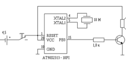
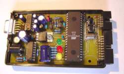
This circuit is so simple, and generated sound may look ugly, but on the other hand, this is a good starting point for newbies with AVR projects. This circuit is made of one IC AT90S2313 (may be substituted by Attiny2313). The circuit is low power and reliable as it consists of very few parts (if SMD chip used, then it can be placed inside a postcard): A microcontroller can be powered by using from 2.7 to 6 V power supply. If the AT90S2313 microcontroller is used, then you need to connect a crystal resonator. If ATtiny2313 is used, you can use an internal RC clock source and reduce the number of parts needed. Transistors can be any general-purpose transistors. If the sounder requires less than 20mA of current, you may connect it directly to the port pin. After reset, the circuit starts the program and plays a melody one time. After that, it goes to power-down mode. Crystal frequencies may be chosen from 32768 to 10MHz. Firmware is written for 10MHz. If you use a different clock source, then reduce SoundTab coefficients in the source code and rebuild it. Download Source code

Continue reading

ATMEL AVR ISP programmer that works with AVRStudio4

Probably many AVR software developers that use the AVRStudio4 environment would like to program chips directly from AVRStudio4 using AVRISP. Usually, we use a simplified version of AVRISP that works with PonyProg or AVRDUDE. But here is the solution that can solve this problem. In sixca.com is a populated simplified version of the AVR ISP programmer that works with ATMEL original programming software. IC1 stands for any RS-232 driver like MAX232 or any similar(DS275). The wire from AVR-ISP to AVR board should not exceed 15cm.

Continue reading

AVR serial and parallel High-Voltage programmer

This programmer isn’t widely popular as usually is easier to use the ISP programming method. But sometimes if you need to disable the RESET pin and use it as a regular pin instead or you want to disable or restore SPI fuses that control the ISP programming method, then you will need a High-Voltage parallel programmer of AVR microcontrollers. One of the programmers available on the wide internet is HVProg. This is a redesign of STK500 but without development board components. This programmer supports all available AVR microcontrollers in every programming mode and is compatible with AVRstudio. In HVProg there are two versions of programmer:

Continue reading

avrdude-gui another easy way to program AVR microcontrollers

Avrdude-GUI is a simple graphical user interface(GUI) for avrdude, a command-line tool running on several OS to program the Atmel AVR Microcontrollers. AVRDUDE-GUI is included in the WinAVR toolset and can be used separately to program AVR chips avoiding the command line as it has to be done with plain AVRDUDE. This program has no installation or uninstallation routines. It just has to be in the directory where the avrdude is located. It has almost all functions needed to program AVR microcontrollers effectively. A few things that need to be done are reading fuses and working with single fuse bits. Now you have to define whole fuse bytes what is not very convenient.

Continue reading

Old good AVR delay loop generator program

This is not a new program, but I decided to add it here because I found it very handy in many cases while developing ASM programs. This small program generates delay loops for ATMEL AVR controllers. It’s multilingual – for now, it supports English and German languages. You can change the program’s GUI language by clicking on one of the flags. The program can generate really long delays. I have tried to enter like the 60s for 16MHz – the code generated without problem To generate a delay loop in ASM source code just follow the steps in the left part of the window Enter the number of cycles of the delay loop. You cannot enter the delay time in seconds as the author promised to implement this feature in the future. Click the GO-Button Copy the source to your ClipBoard (Copy/Paste). Watch out for register collisions in your ASM source! If they are used, save values in the stack before or select different ones. An update! It appears that only a third party web version of the tool is available. A link to a web-based delay loop generator

Continue reading

Moving from PonyProg to AvrDude AVR programmer without pain

Probably PonyProg is one of the most popular programming software among AVR microcontroller developers. And this is OK as it is good software with a very intuitive interface and supports many chips like Atmel AVR, Microchip PIC micro, I2C, Microwire, SPI EEPROM. It works well with an AVR ISP adapter, which is easy to build. This is an ideal tool for low budget projects. The only thing that I don like with it, that I need to do additional steps to program the AVR chip: Compile project with WinAVR; Open hex file with PonyProg; Programm the chip; Then I thought- what if I could build and program the AVR chip with a single button press. This is where AVRDUDE comes in.

Continue reading