Stimuli Generator for AVR Studio helps debugging programs in AVR Studio

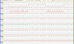
Stimuli Generator for AVR Studio is a handy program that allows making stimuli files for AVR Studio. These files contain information on signals that can be used to affect AVR microcontroller pins virtually. With Stimuli Generator, you can emulate any interfacing like I2C, SPI, and others- this allows you to emulate real-world situations. The program’s working is simple: set target microcontroller (by default 8MHz), set measurement unit- microseconds or milliseconds. For instance, you want to send signals to Pin0 of PORTB. Target MCU -ATMega8, which runs at 4MHz. Set serial interface protocol, which is like start bit length – 60us, bit 0 – 20us, bit 1 – 40us. So, in this case, the step value would be 20us. Step value will depend on what variation on the duration of impulses.

Continue reading

New generation ICprog-AVR2.0 showed up

ICprog-AVR2.0 is a new generation USB AVR microcontroller programmer. The ICprog AVR is the smallest USB Programmer for Atmel AVR Microcontroller available on the market. The version ICprog AVR 2,0 programs with almost double programming speed as conventional programming adapters! The programmer is AVR910 compatible. Two versions of programmers are available: 6-Pin Version with standard AVR910 6-pin header 10-pin Version with KANDA interface

Continue reading

Review on AVR serial and parallel microcontroller programmers

Its been a lot written about AVR microcontroller programmers. This article concludes most common programmers. The easiest programming method is Serial Downloading so-called ISP. This allows to program AVR microcontroller without removing it from the target board. Usually in such boards are a special ISP connector where you connect an external AVR ISP with standard 6 or 10 headers. AVR ISP usually connects to computers COM or LPT port. COM port has the advantage of the ability to use long cables while LPT is limited up to about 1 metter long. But in the other hand, using a COM port requires an additional complementary circuit to match the voltage levels, while the simplest LPT programmer doesn’t need any parts at all: But it is safer to use some kind of buffering circuit like 74HC244 to add some protection from port failure.

Continue reading

AVR microcontroller memory map

AVR microcontrollers are using Harvard architecture. This means that separate memory types (program memory and data memory) are used and connected with distinct buses in this architecture. Such memory architecture allows processors to access program memory and data memory at the same time. This allows increasing the performance of MCU comparing to CISC architecture, where the CPU uses the same bus for accessing program memory and data memory. Each memory type has its own address space: For instance few Atmega series memory map examples:

Continue reading

Programming and customizing AVR microcontrollers

AVR microcontroller programs can be classified by programming method – how to program is loaded into microcontroller from the computer. One is a Parallel programmer (byte by byte). This isn’t a popular programming method. But it is a fast programming method. Using a parallel programmer, you can set fuses that will protect you from using the ISP method. But the main disadvantage of parallel programming is that you have to remove the microcontroller from the circuit. This might be used when producing a series of the same kind of preprogrammed microcontrollers before they are soldered into the board. The parallel programmer can program the RESET pin to be used as a fully functional I/O line; this is why ISP cannot be used after this procedure. Restoring of the RESET function can only be done with a Parallel programmer. The serial programming interface is more convenient for electronics hobbyists. The main benefit of the ISP programmer that you can program the microcontroller directly on board. ISP programmers can be connected to COM or LPT port. COM port is becoming obsolete as it requires additional circuitry, while LPT programmer can be as simple as few wires connecting AVR to LPT port. Popular…

Continue reading

Set up AVRStudio to use AVR-GCC compiler

After the release of AVRStudio4, there is possible to integrate the AVR-GCC compiler into it. As you know, AVRstudio is a powerful tool that has an assembler compiler- debugger, programmer, etc. Integration of AVR-GCC makes this tool a much more powerful and more complete playground for developers. A plugin built-in AVRStudio detects the AVR-GCC compiler by itself, so you don’t have to bother how to tie them together. And here we go – full set of good tools comparable to commercial. The convenient user interface, automatic makefile generation, visual debugging by watching processors register, or even you can flash the chip. How to set up the working environment? This is simple. First of all, you have to download WinAVR20060421 and install it on your machine. Then download AVRStudio Version 4.12 and service pack 3 and install them on your PC. And… that’s it. You are set. Now open AVR Studio and select menu->Project Wizard->New project. In a Welcome AvrStudio4 Screen, select Project Type AVR GCC, enter a project name, select Create Initial file if you want to initial c file to be created. Select Create Folder to put project files in a separate folder. Enter an initial c file name.…

Continue reading

Interfacing PC keyboard to AVR microcontroller

Properties: Interface AVR to standard PC AT keyboard; Only two I/O lines were used. One line is also connected to the external interrupt pin of AVR; No external components are needed for the interface; Included C source reads from keyboard interface and converts to serial In many situations, you need some human interface for your microcontroller project. In this example is interfacing AVR microcontroller to standard PC AT keyboard described. Physically interface looks as in picture bellow: In a keyboard interface, signal lines are an open collector with pull-up resistors.

Continue reading

Connect 6 LEDs using 3 microcontroller pins

Sometimes you need more than you have. I am talking about microcontroller pins. You have to connect 6 LEDs, but you have only 3 microcontroller pins available. To use another microcontroller isn’t always a solution using decoder circuitry isn’t necessary as well. There is a simple hint on how to do this: Connect diodes to the microcontroller as follows: Now, look – if you set one pin to “1” and second to “0” (leave third pin high state – as input pin), then only one led lights on. You can light two LEDs by setting the third pin as an output and state “1” or “0,” which depends on which LED you want to light.

Continue reading

Control memory sections using AVR GCC

Sinewave DDS signal

If you are programming AVR microcontrollers in C, usually don’t think about how the compiled program is stored in microcontrollers’ flash memory. The compiler organizes data in the way it looks optimal. But sometimes, you are working with programs where you need to code chunks located in specific program memory locations. For instance, I faced this problem while developing an AVR controlled signal generator. I wanted to make an efficient and compiler independent main loop where the signal has to be read from flash memory and transferred to port. I managed to use the inline ASM function, which does the job: The linker produces ASM code like this:

Continue reading

Shelling The Intel 8-bit Hex File Format

Intel 8-bit Hex File Format is the most common hex file format used globally, as far as I know. There is also Motorola Hex file format and maybe others. Creating applications with AVR-GCC, we usually select ihex output file format what means Intel hex file format. Let’s go through it and see what’s inside. It is simple as 6 and 6 (six and six) because each Hex file line consists of six parts. And there can be 6 record types in the hex file. Lets go through all six parts of each line:

Continue reading