Easy start with AVR EEPROM using WinAVR

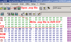
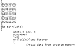
AVR microcontrollers are loaded with some amount of EEPROM (Electronically Erasable Read-Only Memory ) memory. This is a handy feature allowing developers to store program parameters like service information, constants, menu strings, etc. Atmel states that AVR EEPROM memory can be rewritten over 1000000 times. Reading is unlimited. In this article, I am going to show how to store data to EEPROM by defining variables. For this, we need to include eeprom.h header from avr directory (#include “avr/eeprom.h” ). Then we can write a simple variable declaration using the simple attribute EEMEM: EEMEM keyword indicates to the compiler that variables are stored in EEPROM, and it creates a separate .eep file that has to be written to chip separately. Se what I have got after compiling the above code: You can see compiler information about compiled code sizes. The bold line is indicating the size of occupied EEPROM memory. In this particular case, we see that size is 8 bytes: one-byte variable, one word (two bytes), and a five-byte array – total 8bytes. Open .eep file located in the project folder. The compiler compiled Intel Hex File of EEPROM data: :0800000054657374005555109E :00000001FF The first line shows 8-byte data stored at…

Continue reading

AVR watchdog reset timer-practical approach

This is a continuing thread. Why use a watchdog variable timer. This post is about how the watchdog timer on the AVR microcontroller works and how to control it. As we mentioned earlier, the watchdog timer is a distinct timer counter, which generates a reset signal when it fills up. After the watchdog timer counts up to maximum, it generates a short pulse duration of 1 clock cycle. This pulse triggers an internal reset timer counting up to tout.

Continue reading

How to use inline ASM using WinAVR

I have been working on the optimization of one of my C codes. I needed one function to be as optimal as possible. I decided to use inline ASM to achieve this. I decided to write a few lines about this. There are a few rules that are necessary to follow. Each ASM statement is divided by colons into 3(up to four parts): Assembler instructions part; A list of output operands (comma separated); A list of input operands (comma separated); Clobbered register – usually left empty.

Continue reading

Marking of AVR microcontrollers

There is quite a big variety of AVR microcontrollers that ATMEL company produces. This article is about how to Extract information about the AVR microcontroller using its marking on the package. Each microcontroller has its own mark on the package: numbers and letters. The first is the microcontroller type. After follows, a suffix of three fields. The first field is one or two digits, which indicate maximal operation frequency MHz. The second field is a letter showing the package type. And the third field shows the temperature range of the working environment. There are a couple more marking letters “L” and “V” after the microcontroller type. This means that the microcontroller operates at low or very low voltages (and frequencies, of course).

Continue reading

Reading AVR button status using WinAVR

If you want to bring some interactivity to your embedded projects, one option is to add buttons. This allows you to control program flow, set parameters, and much more. Few words about AVR ports. AVR Port pins can be configured as input or output. See table for all general pin configurations: DDRx register is the so-called direction register; PORTx – is port output register; PINx – is pin input register;

Continue reading

Simple routine how to store data in microcontroller flash and read from it using WinAVR

I’ve been asked about how to store data tables in flash memory using the avr-GCC toolset. I decided to post an answer here. Might be someone who find this useful. To demonstrate this I have set up a project using the VMLAB simulator. The files you can download from here: Small project using VMLAB simulator So I created a project in VMLAB. It will help if you read my previous article ho to do this: Using VMLAB as a virtual oscilloscope In project window I have connected 8 LED’s to port D by typing this: D1 VDD PD0 D2 VDD PD1 D3 VDD PD2 D4 VDD PD3 D5 VDD PD4 D6 VDD PD5 D7 VDD PD6 D8 VDD PD7 Then I wrote a simple C program: In program you see, that data can be stored in flash memory using data describing sentence: To make PROGMEM macro work you have to include library pgmspace.h. Bellow you see result of simulation in VMLAB environment:

Continue reading

Internal microcontroller ADC

Many microcontrollers contain internal on-chip ADC. Typical devices would be Atmel Atmega series microcontrollers like Atmega8 and further. Internal ADC is a successive way to integrate the analog world into your embedded systems using only one microcontroller die. Many applications don’t require high speed or high accuracy ADC conversions; thus, on-chip ADC is the best choice. Let’s look at Atmega8. It contains a 10-bit approximation ADC with an analog input multiplexer of 8-single-ended input voltage (refers to 0V) channels.

Continue reading

Design and Implementation of DTMF Detector

Telephone units are ubiquitous. They can be found in almost every house. In some houses with many rooms, a line is paralleled so that anybody can receive and make calls from different rooms. Their presence could be used for other purposes instead of making call per se. This module’s application can be found in the smart home automatic system incorporating a telephone unit as an input module. Using a telephone unit, somebody can control a remote system, as far as the telephone line can reach. To do so, such an interface between the telephone line and the control system is needed. DTMF Detector 2.0 is designed for this purpose. Description DTMF Detector 2.0 is a microcontroller system extension module that detects TMF tones and then decodes the tones into coded binary digits. Using DTMF Decoder, the 2.0 design engineer could interface the analog signal of the telephone line with the microcontroller system’s digital logic in a straight-ahead manner. Module Specifications The module specifications are as follows: 1. Input: DTMF tones from telephone line (analog signal) 2. Output: Decoded binary digits which correspond with DTMF tones. Block Diagram Figure 1 shows the block diagram of DTMF Detector 2.0. The module consists…

Continue reading

7-Segments-Board for Embedded Systems

Design and Implementation of 7-Segments-Board 1.0 – An Extension Module for Embedded System Prototype Introduction When developing embedded systems, it would be helpful if we could have a module for monitoring purposes. For instance, let say that your system has to process data streams. In the testing and verification step, we need to compare each input and output bytes to verify that your system is doing right. Having a monitor module is surely a great help for engineers. Some development board has monitor module integrated, such as Altera UP1X FPGA Development Board. Inspired by its usage and benefit of such a monitor, 7-Segments-Board 1.0 is designed as an extension module for embedded system prototypes. Description 7-Segments-Board 1.0 is a low-cost, low-power MCU extension module for monitoring purposes. It aims to help engineers doing the firmware testing and debugging on hardware prototypes. For those who build microcontroller prototype devices from scratch and do not have access to sophisticated debugging instruments, using this module would make the testing and verification process less painful. 7-Segments-Board 1.0 is designed for an 8-bit microcontroller system. Module Specifications The module specifications are as follows: Input: General purpose push-button (PB) switches (dry contact). Output: Seven-segments LED to…

Continue reading