Atman AVR kick start

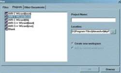
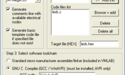
Atman AVR is an integrated c/C++ compiler IDE for Atmel AVR microcontrollers. AtmanAvr C development environment includes ProjectWizard, CodeWizard, Workspace, Output, Text editor, Binary editor, Debugger. The compiler itself is a GCC compiler for AVR. The only thing that makes it commercial is the integrated environment: ProjectWizard – lets you customize a project through series dialogs, and then it generates initial code automatically; CodeWizard – helps in programming routine tasks like creating new modules, adding functions navigating; Advanced workspace where you can find File View, Class View, and I/O View, and many more. If you would like to try this IDE, you may download AtmanAvr C IDE from the manufacturer’s site https://www.atmanecl.com. Bellow is an Atman AVR kick start guide with some screenshots: Create new project File->New: In the Project Name enter the name of your project. Also, select where your project will be located. From tab Projects select one type of projects:

Continue reading

Using VMLAB as virtual oscilloscope

VMLAB is one of the well-known simulators. This is a software simulator of AVR and ST62 microcontrollers. The simulation is far away from real-time, but All timings are tied to real-world values. VMLAB is designed to work as a project. This is a special language (script like), where the circuit is described – where are connections between hardware and microcontroller defined. You may find few prebuilt examples in folders C:\VMLAB\AVR_demo and C:\VMLAB\ WinAVRdemo (If your installation is in C:\VMLAB\ folder). VMLAB is rich in its hardware support: Resistor, Grounded capacitor, Interactive switch/key, LED, Pulsed voltage source, Sine wave voltage source, Slider dependent voltage source (interactive), Non-return-to-zero (NRZ) generator (interactive), Operational amplifier, Comparator, 2 inputs NAND gate, 8 bits D to A converter, RS232 based TTY (interactive), LCD module, I2C monitor (interactive), Interactive keypad 4×4 Multiprocess-dedicated: External Input, External Output. So you can do a wide range of simulations. VMLAB also has a powerful scope where you can watch voltages on pins or even some internal microcontroller resistor values like ACO, TIMOVF signals. Let’s make simple project using VMLAB tool. Start VMLAB And create new project by selecting Project-New. Select project properties like project location, c file name, microcontroller type, software…

Continue reading

AVR microcontroller interrupts using WINAVR

I can’t imagine a microcontroller without interruptions. Without interrupts, you would have to make loops to check if one or another event occurred. Polling has many disadvantages like programs have to make loops, which takes valuable microcontroller resources. These resources may be used for other data processing tasks. This is why the microcontroller comes with built-in interrupt support. Instead of checking events, the microcontroller can interrupt normal program flow and jump to interrupt the service subroutine. During an interrupt, the microcontroller stops the task at the current point, saves necessary information to stack, and gives resources to interrupt the subroutine. When interrupt subroutine finishes, and then normal program flow continues. In assembler your program would start with interrupt table: After the table goes the main program (RESET) and other interrupt subroutines where the program jumps after the interrupt occurs.

Continue reading

ADC on AVR using on chip comparator

Not all AVR microcontrollers come with built-in ADC. But there is a way of building one using an on-chip comparator and timer counter. The comparator compares voltages on +v (Ain0) and -v (Ain1) inputs. If the Ain0 pin’s voltage is greater than in Ain1, then the comparator ACO is set to ‘1’ otherwise, it is ‘0’. Bellow you see AVR comparator circuit. The working of this ADC is as follows. First, PB0 is set to ‘0’ to discharge the capacitor. Then PB0 is programmed as input with no pull-ups, and Timer is started to count.

Continue reading

Programming AVR fuse bits – oscillator settings

I guess many of you were confused when programming AVR fuse bits. I get many newbie questions like “I programmed Atmega8, but it doesn’t work”. Then my standard answer is: “Did you touch configuration bits?” and if yes, then I am almost 90% sure that he did it wrong. Most of them understand wrongly that programmed fuse bit in configuration should be left unchecked and opposite. Let’s take a look at widely used programming software – PonyProg. First thing you do before programming the chip is set configuration bits (Atmega8 in the picture): The first attention should be paid to clock sources. Four bits are controlling Atmega8 clock sources: CKSEL0, CKSEL1, CKSEL2, CKSEL3.

Continue reading

Connect LCD to Atmega using 3 wires

After I implemented interfacing LCD to ATmega8 using 2 wires https://scienceprog.com/interfacing-lcd-to-atmega-using-two-wires/ I decided to make another example but with 3 wires. Using 3 wires makes control much simpler as it is easier to control data flow to shift register. Here I used the same super cheap 74HC164 serial in parallel out register. LCD to shift register is connected in 8-bit mode. LCD strobe pin E is controlled with an Atmega PC2 pin. The register is clocked with PC1, and data is transferred with a PC0 pin. Notice that I used the same data line (PC0) to control the LCD RS pin. RS pin is controlled in this way: after 8 bits are sent to shift register, enable data line by setting ‘1’ (PC0) without clocking and after this LCD E pin is strobed. For more details, take a look at my source code at the end of the article. If there is any questions, don hesitate to ask. Source code:3 Wire LCD interface to ATMEGA

Continue reading

Interfacing LCD to Atmega using two wires

This is not a new idea of interfacing LCD using two wires, but it can help in many situations when there are not enough microcontroller pins. This example is based on the Hitachi 44780 Alphanumerical LCD. This circuit I provide represents an idea, but I think it should also work if soldered. We know that to make LCD working, you need at least 6 (in 4-bit mode) wires to control. But what if you need as many pins as possible from your avr and still want to see results on LCD. Then you need to use a serial LCD or make one. In this example, you need to convert serial data coming to LCD using a shift register. I suggest using the 74HC164. You need only two wires to push data to shift register and then give them to LCD using the “E” strobe signal. How serial LCD operates? Atmega’s PC1 pin clocks shift register, and PC0 is the data line. Before you write to the shift register, clean it by sending “0” in eight clock cycles. You can erase the register with an additional wire controlling register reset, but there would be 3 lines used. After the register is…

Continue reading

Atmega EEPROM memory writing

All mega family microcontrollers have internal EEPROM memory. They can have from 512bytes to 4kBytes. EEPROM memory has its own physical space and is linearly organized. ITo access EEPROM memory in mega, there are three registers used: Address register, Data register, and Control register. Address register EEAR (EEPROM Address Register) comprises two 8 bit registers, EEARH:EEARL. In this register, the EEPROM cell address has to be loaded. Data register EEDR (EEPROM Data Register). When writing to EEPROM, the data is loaded to this register. When getting data from EEPROM – you read data from this register. Control register EECR (EEPROM Control Register) is used to control access to EEPROM memory. EERIE – EEPROM Ready Interrupt Enable. This bit generates an interrupt after the write cycle is finished. If the bit is set to ‘1’ and “I” bit in SREG, then EEPROM Ready interrupt is enabled. If the bit is set to ‘0’ – then the interrupt is disabled. EEMWE – EEPROM Master Write Enable. The EEMWE bit determines whether setting EEWE to one causes the EEPROM to be written. When EEMWE is set, setting EEWE within four clock cycles will write data to the EEPROM at the selected address. If…

Continue reading

Simplest 128 atmega programmer

Atmega 128 is like other AVR microcontrollers. They are ISP – is in-system programmable. Earlier I wrote an article about an AVR ISP programmer where 74HC244 buffer is used. Using buffer is safer for your AVR. But what if you need 128 atmega programmers without any parts? Then you can connect your microcontroller directly to the LPT port or use protection resistors (220R) just in case. of course circuit works without resistors, but you put your LPT port at risk. Just connect GND, SCK, MISO, MOSI, and RESET to adequate LPT pins, and you can program atmega’s flash memory without removing it from a socket. Programming software can be PonyProg

Continue reading