Not all AVR microcontrollers come with built-in ADC. But there is a way of building one using an on-chip comparator and timer counter.
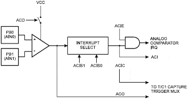
The comparator compares voltages on +v (Ain0) and -v (Ain1) inputs. If the Ain0 pin’s voltage is greater than in Ain1, then the comparator ACO is set to ‘1’ otherwise, it is ‘0’.
Bellow you see AVR comparator circuit.

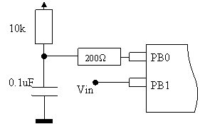
The working of this ADC is as follows. First, PB0 is set to ‘0’ to discharge the capacitor. Then PB0 is programmed as input with no pull-ups, and Timer is started to count.

The capacitor starts charging to 5V through a 10k resistor. When the voltage on the capacitor becomes greater than in input Vin, the comparator state switches to ‘1’. The program detects this and stops the timer counter, and the accumulated count is proportional to the input voltage Vin. If Vin is greater, then the timer counts more, and if Vin is less, then the timer counts less. Just one thing! The voltage on the capacitor rises not linearly but exponentially. But if we restrict the input to the range of like 2.5V, then this voltage raise can be considered linear.

In an example, the RC time constant is 1ms and the capacitor charges 2.5V in about 720us. So this is the worst case of conversion if Vin is equal to 2.5V.
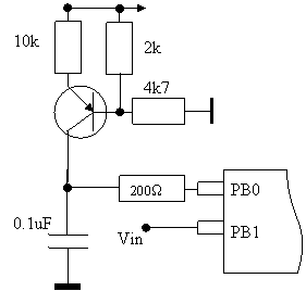
There are techniques for removing the nonlinearity of RC charging. One of them is Transistor current source usage.

In this circuit, the PNP transistor provides a current of about 80uA. Time to charge a capacitor can be calculated as follows: T=(C*5)/I=6.25ms. So iv Vin would be 5V, then conversion time = 6.25ms.
So this takes some conversion time, but for processes like temperature monitoring is suitable.
Note that a 200 Ohm resistor is used to limit capacitor discharging current to protect the port from damage.


