
Joule thief circuit is popular among electronics enthusiasts. It has many implementations but probably the most common is a very minimalist voltage booster based on NPN transistor, coil, resistor, and LED. Its primary intent is to squeeze the remaining juice of dying batteries to light a LED.

Since a pile of dying batteries keeps growing, I decided to give it a try. Instead of building the real circuit blindly, I decided to understand what is going on inside the circuit. So I made this circuit on the LTSpice simulator.
You may find some difficulties when adding a transformer to the circuit, there is an excellent video on how to do this.
Joule thief circuit

In the simulation file, we attached a 1.5V battery. This is the voltage of a new Alkaline battery. But it is not enough to light a LED. Depending on different LED technologies, the forward voltage starts at about 1.85V, and it may be higher for different colors. So Joule thief circuit boosts the voltage to the level which is enough to light a LED.
Joule thief circuit simulation waveforms
Let us see at simulated waveforms and try to explain whats going on here.

In the waveform, you can see three signals:
- Blue is transistor collector voltage
- Green is between the resistor and L1 coil
- Red is the base voltage
From the beginning, when the battery is attached to the circuit base, the current starts to flow through the resistor. It starts to open the transistor, and thus current flows through the second coil L2.
When the transistor is open, the voltage drop on it is about 0.1V. And so coil (and so LEDs) voltage is near zero. The current through the L2 coil and transistor rises, which induces an even bigger current through the base (see high voltage at L1).
Eventually, the ferrite coil magnetic field saturates, and flow in L1 stops increasing. At this moment, L2 stops inducing coil L1. The base current suddenly drops, closing the transistor, which also cuts the current through the L2 coil. But coil is inertial and holds energy, and it starts building voltage due to the collapsing magnetic field in the coil. It rises until it reaches LED break-out voltage, and so it lights up, releasing coil energy.
As you can see, the L2 coil voltage doesn’t rise higher than the diode voltage with some overshoot. This is because LED absorbs energy once it reaches the 3.2V level. You can try adding a different diode like 8V Zener, and you will see that L2 voltage reaches 8V and then drops because the current starts flowing through the diode. The voltage can go much higher, and if you would like to power more energy-hungry devices, you should add more windings to the L2 coil.
When the L2 coil energy is depleted, the base voltage and so current start rising, and the process repeats. Depending on component selection and transformer, joule thief oscillates at tens and even hundreds kHz. Due to the persistence of vision, it seems that LED is always ON.
In practice, such circuit works from like 0.3V
Download LTSpice schematic here: Joule_thief_circuit
Testing real Joule thief circuit
Let us build a Joule thief prototype and see it working in reality.
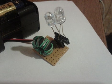
I used about 1cm diameter ferrite ring in the circuit and put 12 turns of each wire. The transistor is standard NPN BC549. The resistor is 320Ω. Probably the trickiest part is making the transformer and connecting the transformer right. In the schematic, you can see that transformer dots are on opposite sides. This means that wires are connected from different ends. Wind eight turns of two wires together until you fill the whole core with one layer. Then take two wires from opposite ends and solder them together. One remaining wire goes to the transistor collector and another to base through the resistor. The size of the ferrite rink may vary – the effect
Here it is working with two series LEDs – white (~4V) and green (~2V):

As you can see no problem to drive two LEDs in series. I also tried to attach three LEDs – they worked, but the intensity dropped drastically. Probably adding wire turns to secondary (L2) coil would be able to deal with this.
Waveforms of real Joule thief circuit
Real measured signals with the scope when the only green LED is lit:
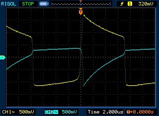
The green wave is base voltage; yellow – collector voltage. As you can see, the collector voltage rises to 3.2V, and then the LED drains the inductor’s power. In this time, base voltage and so current increases slowly and then turns on the transistor.
I hope you enjoyed this little experiment as I did. Please leave a comment on what can be improved here to make joule thief more efficient.