
Different logic levels are a common problem in various circuits. For instance, Arduino boards come powered from 5V or 3.3V. Raspberry Pi is powered at 3.3V, and it accepts and generates 3.3V signals on its GPIO. This is fine until you need to connect the 5V peripheral to a 3.3V device. This can be a simple LCD. Of course, you can get 3.3V LCDs, but this is not always the solution. Sometimes it is handy to build a voltage level converter. It can be a special buffer IC like SN74LVCC3245A. These work great as bidirectional voltage translators.
But in many cases, there is no need for another IC in your circuit. Hobbyists like to go with simpler solutions. The simplest way is to use resistors, where signal levels differ. The fact is that in most cases, devices have clamping diodes on the inputs that are meant to protect a further circuit from over-voltages. For instance, clamping diode inside a 3.3v device will try to limit the input voltage to 3.3V. This is why a series resistor necessary to limit the current flowing through the diode.

Using resistors doesn’t guarantee safe operation. First of all, you must be sure that the 3.3V device has clamping diodes. The second thing is that such a method won’t guarantee bidirectional communications either. If you want to be safe on both sides, you need some converter circuitry in between.
Today I want to discuss the interesting and yet simple method of converting voltage levels using N-channel MOSFET and a couple of resistors. If you have several MOSFET transistors in your box, you can build a level converter right away. This circuit or method isn’t new or fancy. Lots of people already use it, and it works like a charm.
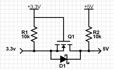
This circuit is known as a bidirectional level converter (shifter). This means that the 3.3V signal is a converter to 5V and vice versa. In-circuit, you also see a Schottky diode, which plays a significant part here. Normally there is a diode inside the MOSFET transistor, so you don’t need to use one additionally. Let us see how this works.
Case 1: when there is a 0V signal from a 3.3V device. At this point, we have a gate voltage of 3.3V. A source at 0V means that the gate voltage is above a threshold and the transistor is conducting. The output line is pulled down through the transistor, and its output also becomes near 0V (We can ignore internal transistor resistance, which is several mΩ compared to resistors R kΩ).
Case 2: When the signal on input is high (3.3V). Then we have source and gate voltage levels the same. This means that it is less than the gate threshold, and the transistor isn’t conducting. So 5V line is pulled to 5V by resistor R2. This way, 3.3V is translated to 5V.
Case 3:In this case, we want to translate the 5V signal into 3.3V. The circuit remains the same. Let’s say we have a high (5V) signal level at the 5V side. The transistor is closed, and both sides are pulled up to corresponding voltages. No big deal here.
Case 4: What about translating 0V from the 5V side to the 3.3V side. This may look a bit more complicated. In this part, the diode plays a significant role. So when we apply 0V to transistor drain, the diode cathode becomes 0V while the anode is at 3.3V due to pull-up resistor R1. So diode starts conducting and thus pulls source pin of MOSFET to almost 0V (there is some voltage drop on the diode). Then transistor gate-source voltage exceeds the threshold, and the transistor starts conducting. And do 0V from 5V side pulls down 3.3V side.
Let’s run a couple of simulations with LTSpice. First of all lets construct a circuit for 3.3V to 5V converter:
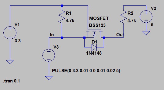
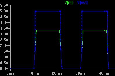
Then run 3.3V periodic signal to its input. And here is result:
Now we fix the power supply for translating 5V to 3.3V:

And here are nice results of level conversion from 5V to 3.3V:

The circuit above is handy in another aspect. Simply speaking, it can be used to convert a higher range of voltages. The lower voltage side is practically limited to the gate-source threshold voltage, which opens the transistor. The higher voltage side is limited to transistor limits. So you could translate like 2V to 15V or so. Be sure that you connect the transistor in the right way – meaning that drain side voltage was always higher or equal to source. Otherwise, the internal diode circuit won’t operate properly.
Download LTSpice simulation file here: 5to33
Hi,
Very good analysis. I do not have access to your simulator, so will just ask you
What is the current that can draw on the 5V side ? can I drive an LED with this circuit on the 5V side ?
Thank you for your excellent job
Marek