
Most microcontrollers have ADC input, which can sample an analog signal, including sound. Even using Arduino, you can do many cool projects using audio information. For instance, you can make a voice-controlled device such as Audio Recorder, voice-activated switch, and more exciting audio-related projects. In this post, I want to focus a bit on the microphone part – the circuit required between the electret condenser microphone and MCU ADC input. Generally speaking, you cannot connect the electret microphone directly to the ADC pin and expect it to work. The part needed here is called an electret condenser microphone amplifier circuit.

Electret microphone with preamplifier stage
Condenser microphones require power from a battery or external source. The resulting audio signal is a stronger signal comparing to a dynamic microphone. First of all, the electret microphone isn’t only a condenser inside. It already has a preamplifier inside usually made of FET transistor, which is connected in common source configuration:

First, the electret microphone needs to be powered through the drain pull-up resistor. Its value depends on the power supply voltage. The rule of thumb is to add 1kΩ per +1V of the power supply. Up to 10V 10kΩ resistor will work fine.
The FET transistor in the microphone needs a negative voltage on the gate to cut-off. So when the voltage is applied through a resistor, some current (~0.2mA) flows through a transistor, which has some resistance value. So it acts as a voltage divider – thus, you get unpredictable DC offset, which varies depending on temperature and selected load resistor.
In such a situation, a microphone is like a current source where the current varies around some DC level. The capacitor on mics output removes DC offset, and you get a low voltage (10-50 mV)AC signal, which needs to be amplified even more. For a microcontroller with 3.3VCC, we need VCC/2 DC offset and max VCC/2 amplitude signal to enter the ADC channel. If we do not look for very high sound and signal quality, simple microphone amplifier circuits will do fine. Let us look at several amplifier circuits and find which is best to use.
Self-biased transistor microphone amplifier
This is probably the simplest amplifier circuit that works pretty well. A self-biased transistor microphone amplifier can be assembled quickly using a few discrete components and breadboard, but there are some things you should consider before choosing it.
Despite its self-stabilizing bias current, this transistor-based amp isn’t that great where ambient temperature changes a lot. Search for a more deep theory about self-biasing problems and benefits on the internet. Despite the negatives, I like this circuit because it is robust and straightforward
Combination or potential Divider Bias microphone amplifier

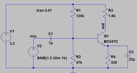
The so-called potential divider bias microphone amplifier circuit has much better thermal stability. The only drawback is that it needs a few more passive components, but a couple more resistors do not mean much if you significantly improve. Let us look at this circuit more deeply to understand how it works and calculate its component values. This circuit has R1 and R2 voltage divider, which produces fixed voltage to the transistor base.
Initially, we know that:
- It is recommended that the current flow through those resistors must be ten times greater than the base current. So R2 = Vb/(10*Ib); and R1 = (VCC – Vb)/(10*Ib).
- Base-Emitter voltage drop is about 0.6V
- Ie = Ib + Ic
- Ve = 10%*VCC;
- Re = Ve/Ie;
- Vb = Ve+0.6;
Having those initial parameters and conditions in mind, we can easily calculate the circuit values for the electret microphone amplifier. If we are going to feed the signal to 3.3VCC powered microcontroller ADC, then our VCC = 3.3V. Let us use general-purpose transistor BC547C which DC gain hfe = 520. lets chose collector current Ic = 1mA.
We need an output Bias voltage = 3.3V/2 = 1.65V.
The we calculate collector resistor Rc = 1.65/1mA = 1650Ω
And select standard resistor value of 1.6KΩ;
Emitter voltage Ve = 10%*3.3V = 0.33V;
As Ic »Ic then we calculate
Re = Ve/Ie = 0.33/1mA = 330Ω
Base voltage: Vb = Ve + 0.6V = 0.33+0.6 =0.93V;
Required base current Ib = Ic/hfe = 1mA/420 = 2uA;
Resistor divider values:
R2 = Vb/(10*Ib) = 0.93/20uA = 46.5kΩ
Standard value R2 = 47kΩ;
R1 = (VCC-Vb)/(10*Ib) = (3.3-0.93)/20uA = 118.5kΩ
Standard resistor value R1 = 120kΩ; Let us build this circuit in LTSpice simulator to see how it is performing:
And its output when microphone signal amplitude is 20mV:
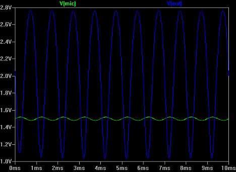
As you can see output DC offset is a bit too high. You might need to tweak resistor divider values a bit to get it right in the middle of 3.3/2 VCC.
Anyway, the non-discrete transistor solutions that use Operational Amplifiers are more popular. They are more stable, generate less noise, and are compact.
The last circuit we are going to look at is a simple OP-amp based microphone amplifier circuit.
Op-amp based electret microphone preamplifier
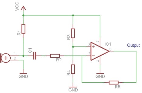
In this case, we are going to use a standard low-power precision operational amplifier LT1215 IC. From its datasheet, we can find that it can be powered from a 3.3V single supply. Let us build an inverting amplifier with middle point DC offset output.
The circuit looks as follows:
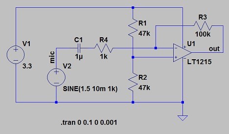
And the signal output:

With an Operational amplifier, calculations are more straightforward. We make a voltage divider with R1 and R2 to the point of VCC. So both resistors are equal. Then we calculate gain resistors by the formula:
Gain = R3/R4.
If we select Gain = 100 and choose R3 = 100k, then R4 is calculated to be 1k.
The importance of input capacitor before the amplifier
We did not mention the importance of the input capacitor, which stands before the amp. First, it is a DC offset filter. If there is an offset DC voltage from the microphone, it is filtered out, and only the AC signal passes through. Also, it performs like a high pass filter along with amplifier input resistance. If you want to capture low-frequency sounds, choose higher value capacitors – 1u, 10, 100u.
LTspice files for simulations: micpream.zip
Sorry, can i ask you something?
where you get the microphone?
And how much the microphone?