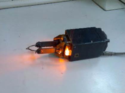
The biggest benefit I see when working with a pulse soldering iron is speed and effectiveness. Of course, when you don’t work, it stays cool; this means it saves energy, doesn’t evaporate poisonous steam, and there is no risk of accidentally burning yourself. Well, this one even has a light source for a better view when soldering. If you like to hack things, you may try this challenge on building a pulse soldering iron.
This iron may be powered from a 220V supply and consumes about 70-100W of power. Efficiency reaches about 50%. The heating time takes 5 seconds while cooling to 50ºC takes about 15 seconds.
Soldering iron may be used in various tasks, including repairing home appliances, replacing electronic parts, etc.

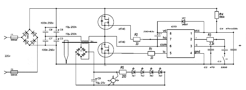
In this pulse iron, there are a self-oscillating half-bridge driver IR2151 used. IRF740 MOSFETS are used to drive current to load. Working of iron is simple. IR2151 generates pulses driven to a transformer, which transfers energy via a diode bridge, and the C filter powers cooler and LEDs. But this power isn’t enough to heat the heating tip. When button S1 is pressed, then values of C2 and C3 capacitors add up this way generator enters the low-frequency phase when the transformer reaches saturation level. At this level of heating, the tip gets enough energy to heat up to a high temperature.

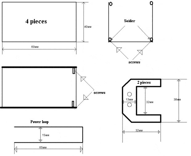
All resistors in the circuit are 0.25W power; just R4 should be at least 0.4W. Recommended color of LEDs is orange as it is best for illuminating circular cracks. The diode bridge should consist of 1A and 400V diodes. Cooler any 12V – any smaller PC cooler. The transformer is made of two Ш shape core 30x30x6 2500HM. The primary coil contains 65 windings of 0.25mm2 and the secondary 4- 5 windings of 0.25mm2. Power winding is made of copper plate 135x10x1.5mm and bent. The tip is made of 1.5mm copper wire, which is crewed to the copper plate to make a loop for current from the transformer.

After the solder is assembled, you need to choose the proper C3 capacitor. To do this, just disconnect the soldering tip and connect the 40W light bulb. When button S1 isn’t pressed transformer should be ticking silently, LEDs ON and cooler ON, but the light bulb should be OFF. When the button is pressed, the transformer should stop ticking, LEDs should light more brightly, and the cooler runs faster, but the light bulb should not light on. Then C3 should be a lower value like 2200pF or take a smaller R3 resistor value.
If everything works, then finish all cosmetics, including cooler, coating PCB with painting to prevent short-circuit (anyway, you’ll be holding the device in your hands). And be careful as it is a high voltage device. The author doesn’t take any responsibility for any injuries.


vreau sa stiu mai exact cum se face transformatorul mai bine spus daca se poate poze
How made transformer I want pictures detailed please