Simple dummy load for basic testing

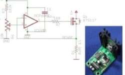
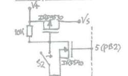
I bet you face many problems in the design process where you need to test the power supply or LED by providing/drawing constant current regardless of voltage change. Such a device is called a dummy load. You can find lots of DIY dummy load projects, and we won’t be talking about commercial ones right now. Nick found out that most DIY dummy loads tend to be complicated or unavailable. So without struggling, he decided to start his own simple and reliable load. He wanted it to be simple, self-powered, and indestructible. Indestructible means that it won’t burn in a voltage range up to 30V. With BTS141 FET this became possible as it has built-in over-current and over-voltage protection built-in. Controlling is done with a simple potentiometer attached to operational amplifier positive input. Negative input is connected to the current sense resistor. The project is OSHW which can be found on Github as re:load. [source]

Continue reading

Fractal antenna technology

A Fractal receiver is a receiver that can be damaged up into lesser parts. Fractal means a part of, so in this scenario, they refer to a receiver that can have feelers added or aloof. By liability, the Fractal receiver is; next, a notion called the self-similarity to expect module. This typically means that you can detach or add in peer parts. If you ever took a lobby in Fractal Geometry, you’d learn the mathematical reasoning behind this. The Mandelbrot Set governs the mathematics behind this stunt. Benoit Mandelbrot is the father of fresh day Fractal Geometry. These antennas activate by elate out rare electromagnetic signals that face a specific zone or size depending on how many Fractals the receiver has. Fractal Antennas aren’t outsized or awkward in any way. They are tiny and have legal world applications in cellular phones or microwave ovens and another small electronic method. This receiver is rare in that it can activate at countless different frequencies at the same time.

Continue reading

Building simple power supply from theory to working example

A power supply is an essential part of every electronic device. The whole system relies on it. If a power supply fails – the device dies too, and there is a chance that sensitive parts may be damaged. Power supply solutions vary from device to device. They may work using different techniques depending on needs. Tim has described probably the simplest power supply solution, which converts Alternating Current (AC) to Direct Current (DC). The supply circuit consists of well-known parts – transformer, which transforms voltage from 230V AC to 12VAC, follows diode bridge rectifier, smoothing using large caps and regulation with standard 7805 voltage regulator. Such a solution proved itself in many designs. It is simple, cheap, and builds fast. Tim put everything in the short and informative post without overhead information. Following it, you will be able to construct a 5V DC power supply in an hour.

Continue reading

12V solar charger using LM317

[Alex] decided to build a solar charger for his car battery. He had an 18V solar panel able to provide up to 83mA. You cannot connect the panel directly to the battery because charging voltage cannot exceed the allowed safe limit, and also solar panels may become a load for the battery in a dark time, and this way discharge it. So he ended up with a simple circuit utilizing LM317 and a couple of resistors setting voltage so that battery would be charged at the recommended 13.2V. To prevent back supply, a Schottky was used. Of course, it adds some voltage drop (0.7V worst case). This was taken into account while calculating voltage adjusts resistor divider. As a test [Alex] left a solar charger for three days connected to his battery, and it charged up to 12.35V which is about 75% of capacity. Not bad at all.

Continue reading

Adding self power down functionality to your devices

The power-down feature is convenient on battery-operated devices. For instance, most of the multimeters already have this feature allowing them to self turn off when there is no activity for some time. Check out this simple solution, which uses a pair of FETs and resistors. It was initially made for the Atmega328 project because the author didn’t want to bother with AVR power-down modes. Instead, he used this simple circuit. It can be used to turn the device on with the switch. This is where the P-FET part plays a role and turn off with N-FET. Turn Off signal wire comes from AVR pin market as 5. While the device is powered, N-FET has to be on with a high gate signal. When the N-FET gate signal goes low device turns itself off. This can be used on any device where possible to get such signal conditions. Or use in microcontroller circuit by adding some delay count after inactivity.

Continue reading

Avoid smoke with power protection circuit

When designing an electronic device, you want to make sure that it won’t go in smoke under unexpected circumstances. You never know what may go wrong during the device’s lifetime, primarily if it is powered from mains. The small circuit between your battery and device may protect it from mistakes like reverse power polarity. His lists start with a simple series diode, which is cheap but may help protect from reverse polarity. Like any other, it has a downside – voltage drop (0.7V) that may be a pain for low voltage devices.

Continue reading

Multivibrator – back to basics

Multivibrator circuit is one of the first projects you start learning electronics. It is a beautiful circuit widely used for educational purposes and even in end projects as waveform generators. Lots of hobbyists grab a microcontroller/Arduino to blink LEDs. But using basic circuits like multivibrator may be cheaper, faster, and even fun. [Ray] decided to go through multivibrator theory and explain its working in detail step by step. The circuit itself consists of two transistors, two capacitors, and four resistors. When powered, the circuit generates a square wave signal that can be used to flash LEDs or clock other circuits. You will get an intuition on what causes multivibrator to develop generate. Formulas allow calculating resistor and capacitor values for a particular frequency. If you are a starter in electronics, build one on a breadboard and do some experiments, why not start with Christmas lights.

Continue reading

Transistor based class AB amplifier

In most small audio projects, hobbyists are using specialized audio amplifier chips. That’s really fine; you get high-quality amplification without scratching your head. Some probably don’t care how these things work. But don’t forget that amplifiers can be built out of discrete electronics components like bipolar transistors. Check out this great hack week project where Dino makes a class AB audio amplifier out of three bipolar transistors and other passive components. He slightly goes through the theory of operation and, of course, demonstrates its working in the following video.

Continue reading

Adding DAC to Arduino or any other microcontroller

Most of the 8-bit microcontrollers lack integrated DAC (Digital to Analog Converter) functionality. This is handy when you need to generate analog signals out of digital information. Adding DAC to any existing microcontroller is a piece of cake. But before you start, why not look at various options available. Embedded newbie provides a review of Arduino DAC solutions. Beginning with the R-2R ladder solution list goes through multiple ways of converting digital to analog. Depending on your needs and the speed required, a PWM DAC converter is nothing more than a digital signal passed through a low pass filter. This is how motor control works. It’s relatively slow, but serial that gives an advantage when small pin count microcontrollers are used. On the other hand, if signal speed is an issue, then parallel DAC – same R-2R ladder probably with an output buffer circuit. And lastly, there is always an option to use specialized DAC chips that can be interfaced through one of the available interfaces like SPI. These save space and MCU pins and still provide high resolution and speed.

Continue reading

MSP-EXP430FR5739 board have just arrived

Over a week ago, I got a notice that Texas Instruments (TI) is giving away a 50% coupon for MSP430_FRAM related devices. Without hesitation ordered their MSP-EXP430FR5739 TI experimenters board that price went down to $14.50, including free shipping. With all functionality and onboard peripherals included – it’s a giveaway. The experimenter’s board came in an excellent complex paper package that feels really solid and professional in hands.

Continue reading