The Unbelievable Xbee 900 rf
The Basic Knowledge You Should Know about Pulse Width Modulation!
Circuit Diagram
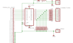
A circuit diagram is also known as an electrical diagram, wiring diagram, elementary diagram, or electronic schematic. It is a simplified conventional symbolic representation of an electrical circuit. It shows the circuit components using easily understood symbols and the power and signal connections between the devices. The components’ arrangement and their interconnections on the diagram do not correspond to their physical locations in the finished device. Unlike a block diagram or layout diagram, a circuit diagram shows the actual wire connections being used. The chart does not in any way represent the physical arrangement of components. Circuit diagrams are used for the design, construction, and maintenance of electrical and electronic equipment.
Analog Circuit Design
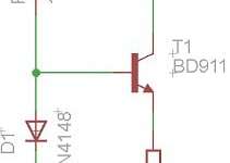
Today’s modern circuit design is a bit of a conglomerate thanks to the availability of sophisticated process technologies that have made bipolar and CMOS (Complementary Metal Oxide Semiconductor), power and signal, passive and active components available, all on the same die. From this point on, it is up to the circuit designer’s ingenuity to assemble these components into the analog and/or logic building blocks that are deemed necessary to develop the intended system on a chip.
DS1803 Digital Potentiometer – The Great Variable Resistor

You’re still frustrated with your old-fashioned and limited functions potentiometer? Instead of being annoyed by it, why don’t you spend several hours making a DS1803 digital potentiometer? With this DS1803 digital potentiometer, you can easily control the resistance over its range in the programmable action and then send it commands over a 2-Wire (12C/TWI) serial interface in a second! This means you can hook it up to another microcontroller, such as the most popular Arduino, and then adjust the program’s resistance. It would be best if you chose DS1803 because it is compatible with the program, it can be operated in either 3V or 5V, and you can choose from a few different models with various resistance ranges. For the project, you can create a tiny PCB, were consists of two DS1803s. You will get four potentiometers on this board since each of the DS1803 has two potentiometers!
DIY an USB Audio DAC and Leave More Green Cow in Your Wallet!
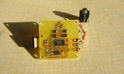
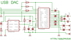
Have immensely interest in the audio DAC design, and would like to DIY a low cost but powerful audio DAC? Ok, now you have the chance, as you’ll learn to create your very own audio DAC today. You will use the circuit PCM2902 for this project, where you will need to design the DAC from USB with this circuit on a one-sided PCB! Since the circuit board is a well designed wrong board, everything besides the crystal and USB connector will be placed from the bottom. Below here is the schematic diagram from datasheet of PCM2902.
DIY Class A MOSFET Headphone Amplifier Can’t Even Be Easy Than Before!
You’re not satisfied with your desktop headphone amplifier? Then, just stop the complaint and DIY Class A MOSFET headphone amplifier! First, you will need to use a regulated power supply, which can be purchased from Radio Shack (10-20VDC and 750mA should be OK). The regulated power supply is responsible for regulating the power supply will ripple the rejection and eliminate any noise in the power supply. An IRF610 MOSFET and an LM317 regulator will be used in the Class A Mosfet headphone amplifier. Here is the step-by-step guide for the project; let’s get started… Firstly, you have to prepare an external CD-ROM (It would be better to have a power switch, power adapter receptacle, RCA inputs on the back, and headphone jack on the front). The amplifier is constructed on 2″ square protoboards from Radio Shack. You will need to assemble these components onto the board:
The Good Helper for Pressure Sensor – DIY Force Sensitive Resistor (FSR)
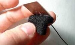
Do you wish to have a thin, accurate, and durable Force Sensitive Resistor (FSR) to help you to sense the surface pressure? Well, would you want to spend over $50 for just an adequate quality FSR, while you can DIY it with less than $20 here? First of all, you have to prepare the require tools and components: Tools
DIY Sound Card – Is Time For You to Blast Off The Music
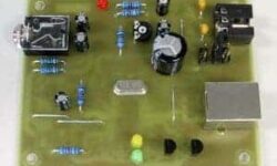
Do you think making a sound card is a complex and impossible mission? Then, you’d better think again… If you use the IC PCM2702 from Texas Instruments, you will create a powerful and well-built USB sound card. The best thing about a DIY USB sound card is you don’t need to install any driver for Windows XP/Vista, as they are already built-in. Just plug and play it! This construction’s central core is a 16-Bit Stereo Digital-To-Analog Convertor with the USB interface PCM2702, of course. You need several additional parts to work with the PCM2702, and it’s not complex as you’ve thought here. The sound card can be powered directly from the USB port (jumper W1) or the external power supply (jumper W3). Two power supplies, 3.3V (3V-6V) and 5V (4.5V-5.5V), are needed for PCM2702.


