Running multiple FreeRTOS tasks on AVR
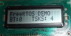
In the previous post, we just run a single task. Running RTOS with a single task has no meaning at all. This can be quickly done with a conventional program. But what if we need to have more separate functions. To execute them at exact timing would require a separate timer or interrupt. But microcontroller cannot guarantee an interruption for every task. This way, it is hard to make code modular, and testing can be painful. Using RTOS solves this kind of problem. It allows programming each task as an endless loop. Kernel scheduler takes care of assuring each task gets its chunk of processing time. Additionally, it does bearing the priority systems – more critical tasks are executed before less important ones. Let us go further with our example code and add more tasks to our FreeRTOS engine. We already have an LED flashing task that toggles LED every second. Additionally, we are going to create another task that checks the button state. Also, we are going to send some information to the LCD. As always, let’s take care of drivers for all of them.

Continue reading

Using FreeRTOS kernel in AVR projects

FreeRTOS is known as Real-Time Operating System. It would probably be too dare to call it real-time-os, preferably a real-time scheduler where applications can be split into independent tasks that share complete processor resources by switching them rapidly. It. It looks like all functions are executed in parallel. This feature is called multitasking. There are many debates on using RTOS on AVR microcontrollers as they are arguably too small for the running scheduler. The main limitation is a small amount of ram and increased power usage. If you use lots of tasks in the application, you will probably run out of RAM to save context when switching between tasks. Consider FreeRTOS only if you use larger scale AVRs like Atmega128 or Atmega256. Indeed you can find smaller schedulers that are specially designed for smaller microcontrollers, even tiny series. On the other hand, if you master FreeRTOS, it can be used with multiple microcontrollers like ARM Cortex, PIC, and various compilers, including IAR, GCC, and Keil Rowley, Attolic. And the main reason to keep an eye on it – it is free. Probably it would take lots of time and space to go through RTOS theory. Some great information can be…

Continue reading

Getting hands on Arduino Ethernet Shield

Probably everyone knows Arduino and perhaps using it. This development platform is worth its popularity. Probably the best thing about it is open-source ideology. Indeed it is an excellent development platform that includes software and hardware solutions where even non-electronics guru can master great projects. In a few years, Arduino has grown in a great community around the world. And that is great – this means that you have access to endless resources, endless project ideas and lots of members willing to help if you are stuck with something. All the necessary information you can always find in https://www.arduino.cc/. OK, enough of talkies. Let’s see what we have here. Thanks to SparkFun electronics, Arduino Duemilanove stands on my table fully assembled and ready to work. I decided to give a try on Arduino Ethernet shield based on Wiznet W5100 chip. It has a library, so you don’t need to think of details how Ethernet chip is controlled. Few lines and you have some info in your favorite browser.

Continue reading

Temperature sensor with time and date display on graphical LCD

Some time ago, I built a prototyping board with a graphical LCD. It has served for various small projects and prototypes. I had a spare temperature sensor DS18B20 and decided to put on a simple temperature display project. GLCD board is equipped with an Atmega32 microcontroller running at 16MHz. DS18B20 sensor is connected to port D pin 6. LED connected to PD3 is used for indicating EEPROM write activity. The device is navigated with a rotary encoder. It is connected to MCU as follows (more about interfacing rotary encoder here):

Continue reading

Running TX433 and RX433 RF modules with AVR microcontrollers

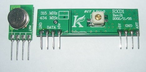
Sometimes in embedded design, you may want to go wireless. Maybe you will want to log readings of remotely placed sensors, or build a remote control for a robot or design an alarm system. Radio communications between two AVR microcontrollers can be easily set up with specialized modules. Let us try to run very well-known RF modules TX433 and RX433 (or similar) that can be found almost in every electronics shop. The pair of them cost less than 15 bucks. Transmitter and receiver modules are tuned together to work correctly at the exact 433.92MHz. The transmitter can be powered from a 3 to 12V power supply while the receiver accepts 5V. The 5V is standard for AVR microcontrollers, ideal for 5V devices. Modules do not require additional components – apply power and connect a single data line to transmit data.

Continue reading

DS1803 Digital Potentiometer – The Great Variable Resistor

You’re still frustrated with your old-fashioned and limited functions potentiometer? Instead of being annoyed by it, why don’t you spend several hours making a DS1803 digital potentiometer? With this DS1803 digital potentiometer, you can easily control the resistance over its range in the programmable action and then send it commands over a 2-Wire (12C/TWI) serial interface in a second! This means you can hook it up to another microcontroller, such as the most popular Arduino, and then adjust the program’s resistance. It would be best if you chose DS1803 because it is compatible with the program, it can be operated in either 3V or 5V, and you can choose from a few different models with various resistance ranges. For the project, you can create a tiny PCB, were consists of two DS1803s. You will get four potentiometers on this board since each of the DS1803 has two potentiometers!

Continue reading

Show Your Talent by DIY a Sun Tracking Unit

Probably you saw the Sun tracking system before; however, do you have the urge to challenge yourself to make a Sun Tracking Unit? First of all, get a tiny .7″x1.4″ PC board using the LED3X sensor concept. This circuit uses power MOSFET drivers, which most any DC motor can be used without any modification. You might notice that the power drivers are good enough for delivering about 50 amps of peak current or even more. The current will increase accordingly to the transistor. This means the large power MOSFET, 72A, when operated in low power mode, will eliminate the transistor’s need for a heat sink. Cool, isn’t it?

Continue reading

AVR DDS signal generator V2.0

Finally, the second version of the improved AVR DDS signal generator is here. THE first AVR DDS V1.0 generator was only an attempt to run the DDS algorithm without any analog amplitude control. In this DDS generator version, I still wanted to keep things as simple as possible using a minimum count of widely available components in the updated circuit. Also, I kept a single-sided PCB approach. AVR DDS specification AVR DDS signal generator V2.0 is a firmware-based DDS signal generator that uses a slightly modified Jesper’s mini DDS algorithm adapted to AVR-GCC C code as in-line ASM. The AVR DDS signal generator has two outputs – one for DDS signal and another for high speed [1, 8MHz] square signal – which may be used to bring back to life microcontrollers with wrong fuse settings for other purposes where a high-speed square signal may be needed. A high-speed (HS) signal is output directly from the Atmega16 OC1A(PD5) pin. The DDS output is used for all complex signals generated via the R2R resistor network and is adjusted via LM358N offset and amplitude regulating circuits. Two potentiometers can control offset and amplitude. The offset can be controlled in range +5V..-5V while magnitude…

Continue reading

DIY AVR Graphical LCD test board

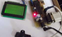
Once I’ve got several HQM1286404 graphical LCDs around, I decided to build a prototyping board where I could easily plug LCD to it, read data via ADC and display graphs, and plug keypad if needed for some menu functions. Earlier, I tested graphical LCD on prototype breadboard but dealing with multiple wires (GLCD needs 20) resulted in many failures. It is OK to do simple tasks, but more complex applications require a more stable platform. So here it is: This type of GLCD is a standard 128×64 pixel matrix controlled by the KS0108 LCD controller. I have a smaller non-common pin-header where pins have 2mm step, so I had to draw it for Eagle library, which you will find in project files. I decided to make a simple circuit so it could fit in 100x50mm single-sided PCB. As base MCU, I used Atmega16, which can be replaced with Atmega32, which is pin-compatible with Atmega16 have more data memory.

Continue reading