
Sometimes in embedded design, you may want to go wireless. Maybe you will want to log readings of remotely placed sensors, or build a remote control for a robot or design an alarm system.
Radio communications between two AVR microcontrollers can be easily set up with specialized modules. Let us try to run very well-known RF modules TX433 and RX433 (or similar) that can be found almost in every electronics shop. The pair of them cost less than 15 bucks.
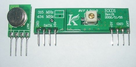
Transmitter and receiver modules are tuned together to work correctly at the exact 433.92MHz. The transmitter can be powered from a 3 to 12V power supply while the receiver accepts 5V. The 5V is standard for AVR microcontrollers, ideal for 5V devices. Modules do not require additional components – apply power and connect a single data line to transmit data.
For better distances, attach 30 – 35cm antennas. Modules use Amplitude-Shift Keying (ASK) modulation method, which uses 1MHz bandwidth.
Interfacing TX433 and RX433 modules to AVR
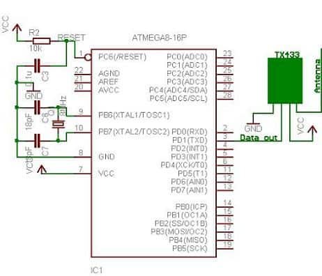
I have constructed two separate test circuits on Atmega8 microcontrollers.
The transmitter
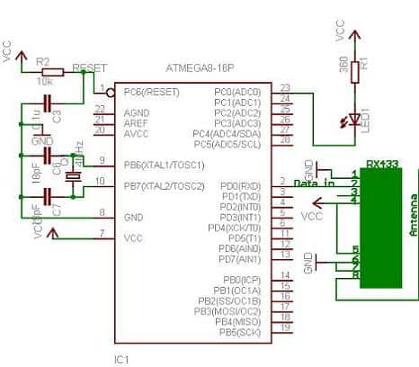
And receiver
The test rig was assembled on a prototyping board and breadboard.
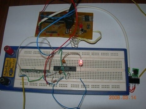
As you can see, I have used one LED for indicating RF activity. Once the hardware part is ready, we can proceed with the software part.
Writing AVR C software for RF modules
Radio transmission is a bit more complicated than wired communications because you don’t know what type of radio signals are present on air. It all matters how the transmitted signal is encoded.
Here you have many choices: use hardware encoding like USART or write your own based on one of many available encoding methods like NRZ, Manchester, etc.
In my example, I have used the AVR USART module to form data packs. Using hardware encoders solves many problems like synchronization, start and stop, and various signal checks. However, you cannot rely on plain USART signal encoding. You may lose synchronization, for instance, if you send all zeros in the packet and so on. Here you can improvise by adding various checks and so on.
I decided to form 4-byte data packets to send one-byte information. These include:
- one dummy synchronization byte (10101010);
- one address byte – in case there are more receivers(or transmitters);
- one data byte;
- Last checksum byte, which is a sum of address and data (address + data).
Why did I use a dummy byte at the beginning of the package? When the transmitter does not transmit any data – the receiver catches various noises coming from the power supply or other sources. The receiver likes to adjust its input gain depending on the input signal level, so we need to pace things a bit. First-byte tunes receiver to accept normal signal levels then we send an address byte, data, and checksum. With different transmission modules, you may exclude this dummy byte or use different encoding strategies.
Transmitter program for AVR Atmega8
#include <avr/io.h>
#include <util/delay.h>
#ifndef F_CPU
//define cpu clock speed if not defined
#define F_CPU 8000000
#endif
//set desired baud rate
#define BAUDRATE 1200
//calculate UBRR value
#define UBRRVAL ((F_CPU/(BAUDRATE*16UL))-1)
//define receive parameters
#define SYNC 0XAA// synchro signal
#define RADDR 0x44
#define LEDON 0x11//switch led on command
#define LEDOFF 0x22//switch led off command
void USART_Init(void)
{
	//Set baud rate
	UBRRL=(uint8_t)UBRRVAL;		//low byte
	UBRRH=(UBRRVAL>>8);	//high byte
	//Set data frame format: asynchronous mode,no parity, 1 stop bit, 8 bit size
	UCSRC=(1<<URSEL)|(0<<UMSEL)|(0<<UPM1)|(0<<UPM0)|
		(0<<USBS)|(0<<UCSZ2)|(1<<UCSZ1)|(1<<UCSZ0);
	//Enable Transmitter and Receiver and Interrupt on receive complete
	UCSRB=(1<<TXEN);
}
void USART_vSendByte(uint8_t u8Data)
{
    // Wait if a byte is being transmitted
    while((UCSRA&(1<<UDRE)) == 0);
    // Transmit data
    UDR = u8Data;
}
void Send_Packet(uint8_t addr, uint8_t cmd)
{
	USART_vSendByte(SYNC);//send synchro byte
	USART_vSendByte(addr);//send receiver address
	USART_vSendByte(cmd);//send increment command
	USART_vSendByte((addr+cmd));//send checksum
}
void delayms(uint8_t t)//delay in ms
{
uint8_t i;
for(i=0;i<t;i++)
	_delay_ms(1);
}
int main(void)
{
USART_Init();
while(1)
	{//endless transmission
	//send command to switch led ON
	Send_Packet(RADDR, LEDON);
	delayms(100);
	//send command to switch led ON
	Send_Packet(RADDR, LEDOFF);
	delayms(100);
	}
	return 0;
}
In my case, I used the UART 1200-baud rate. It may be increased or decreased depending on distance and environmental conditions. For the longer distances, lower baud rates work better as there is a more significant probability for transmission errors. The maximum bit rate of the transmitter is 8kbits/s, which is about 2400 baud. What works in theory usually does not work in practice — better stick with 1200 baud – a maximum of what I could get working correctly.
Transmitter sends two commands (LEDON and
Receiver program code
#include <avr/io.h>
#include <avr/interrupt.h>
#include <util/delay.h>
#ifndef F_CPU
//define cpu clock speed if not defined
#define F_CPU 4000000
#endif
//set desired baud rate
#define BAUDRATE 1200
//calculate UBRR value
#define UBRRVAL ((F_CPU/(BAUDRATE*16UL))-1)
//define receive parameters
#define SYNC 0XAA// synchro signal
#define RADDR 0x44
#define LEDON 0x11//LED on command
#define LEDOFF 0x22//LED off command
void USART_Init(void)
{
	//Set baud rate
	UBRRL=(uint8_t)UBRRVAL;		//low byte
	UBRRH=(UBRRVAL>>8);	//high byte
	//Set data frame format: asynchronous mode,no parity, 1 stop bit, 8 bit size
	UCSRC=(1<<URSEL)|(0<<UMSEL)|(0<<UPM1)|(0<<UPM0)|
		(0<<USBS)|(0<<UCSZ2)|(1<<UCSZ1)|(1<<UCSZ0);
	//Enable Transmitter and Receiver and Interrupt on receive complete
	UCSRB=(1<<RXEN)|(1<<RXCIE);//|(1<<TXEN);
	//enable global interrupts
}
uint8_t USART_vReceiveByte(void)
{
    // Wait until a byte has been received
    while((UCSRA&(1<<RXC)) == 0);
    // Return received data
    return UDR;
}
ISR(USART_RXC_vect)
{
	//define variables
	uint8_t raddress, data, chk;//transmitter address
	//receive destination address
	raddress=USART_vReceiveByte();
	//receive data
	data=USART_vReceiveByte();
	//receive checksum
	chk=USART_vReceiveByte();
	//compare received checksum with calculated
	if(chk==(raddress+data))//if match perform operations
	{
		//if transmitter address match
		if(raddress==RADDR)
			{
				if(data==LEDON)
					{
						PORTC&=~(1<<0);//LED ON
					}
				else if(data==LEDOFF)
					{
						PORTC|=(1<<0);//LED OFF
					}
				else
				{
					//blink led as error
					PORTC|=(1<<0);//LED OFF
					_delay_ms(10);
					PORTC&=~(1<<0);//LED ON
				}
			}
	}
}
void Main_Init(void)
{
	PORTC|=(1<<0);//LED OFF
	DDRC=0X001;//define port C pin 0 as output;
	//enable global interrupts
	sei();
}
int main(void)
{
	Main_Init();
	USART_Init();
	while(1)
	{
	}
	//nothing here interrupts are working
	return 0;
}
The receiver program receives all four bytes, then checks if the checksum of received bytes is the same as the received checksum value. If the checksum test passes, the receiver address is compared, and if it matches a device address, it starts analyzing data.
RF transmission results with scope images
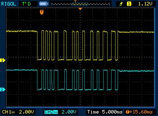
After all, I have noticed that without antennas, the transmission is more erroneous even if modules are standing nearby. Of course, with all the power noise from chords lying around the room, I was getting lots of noises that the receiver was catching between data transmissions.
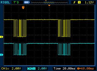
In the last pictures, you can see data packets of 4 bytes viewed on the oscilloscopes. Yellow signal is from the transmission data line (TX) while blue is taken from the receiver data line (RX):
Good luck if you will decide to go wireless!