AVR based TDA7313 Audio processor control

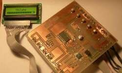
TDA7313 audio processor has been used for more than ten years because of its simplicity, functionality, and proper parameters like low distortion and low noise. Chip is based on BIPOLAR/CMOS technology and can be used in various applications, including car radios, Hi-FI, simple mixers. TDA7313 chip has three external stereo inputs that allow multiplexing three incoming sound sources. It has a volume control with steps of 1.25dB, Treble and BASS control, Loudness function. Each of the four outputs has a distinct control that allows balancing outputs. A chip can be controlled via an I2C (TWI) interface. Description of Audio processor This project’s idea was to construct an independent audio processor that can be embedded in any sound system with the ability to control settings with a simple button interface with a menu preview in LCD. The intent was to cover all audio-processor functionality within the LCD menu.

Continue reading

Controlling graphical 128×64 LCD based on KS0108

HQM1286404 is a pretty old graphical LCD module, but it is still popular. KS0108 driver controls this LCD. LCD backlight color is yellow-green. I think this is an excellent choice for many projects where graphical information is needed for several reasons – you can find libraries around the internet to start working in just a few minutes. Several tools can also be used to generate character arrays and graphics. The hardest thing for me was to find the correct wiring as the datasheet I have was for the next PCB revision (HQM1286405) as mine are HQM1286404, so don’t be mistaken as I did. Here is the correct pin-out of LCD:

Continue reading

DIY 4x22W car audio amplifier based on TDA7384

I decided to make a pretty simple but powerful enough audio amplifier. For this, I’ve chosen quad-bridge car audio amplifier IC – TDA7384, which has four input and four output channels with a power capability of 4x35W. If connected to a car battery where the operating voltage is about 13.2V, then each channel can give 22W what is more than enough for me. This amplifier I probably will use to test audio processor TDA7313, which is still in the development phase. I didn’t find much information about this chip on the internet, so I decided to build it and try it independently.

Continue reading

AVRJTAG clone in action

Building AVR Jtag clone Finally, I found some time to finish the AVRJTAG clone. It was hanging for a while on a breadboard with a bunch of wires. I have made an Eagle CAD project with a PCB layout you will find at the article’s bottom. I didn’t change the circuit very much from the previous, just added ISP header(but didn’t have a chance to test it) and transferred to Eagle project as I didn’t find one ready to build:

Continue reading

IR remote control signal receiver using AVR microcontroller

IR remote control is a device you can find everywhere to find a TV, VCR, or home theatre. Why not use one of them for controlling your own devices like light, air conditioning, etc. As we know, remote control devices use IR light. This is invisible light of about 950nm wavelength. One most significant problem in using IR light is that there many other sources of it like the sun, light bulbs, fire. To exclude other sources, the IR signal is modulated by some frequency. The receiver has to be tuned for this frequency. Mostly remote controls transmit IR signals using 36kHz frequency signals. Transmitting and coding is one part that can be done more efficiently than receiving and decoding. Decoding is usually performed by using microcontrollers. First of all, the receiver has to get rid of the 36kHz carrier frequency. This is not a simple task to demodulate the signal; this is why particular IR receiver IC’s are produced. One of them is TSOP1736:

Continue reading

Build your own AVR JTAG ICE clone

After unsuccessful attempts to run a few programs which drive peripherals like USART and Timers on Atmega128, I decided to make a JTAG debugger. I hope it will allow me to see what is happening may atmega128 corrupted, or something is wrong with the software or hardware. The most widely used AVR JTAGICE clone is AVR miniICE, which is compatible with the original AVR JTAGICE. AVR JTAG is mainly used for target board debugging in the real world. And of course, you also can program your AVR’s with it.

Continue reading

Build Piconomic Atmega128 development board by yourself

First of all, I have ordered to make PCB by using a milling-drilling plotter. Of course, I could make the board by myself, but I wanted to save some time and nerves in case of errors. After one week my board was shipped to me: Then I bought all parts needed. One thing that didn’t go well was that I couldn’t get capacitors and resistors in SMD packages 0603, so I used 0805 to lie on the side.

Continue reading

Simple TTL to RS232 adapter

During my spare time, I made a quick TTL design for an RS232 adapter that works with my AVR development board. This adapter helps to connect TTL (Transistor-Transistor Logic) level signals to the RS232 interface. TTL side is a 9-pin female connector, and RS232 sire is a male connector. The unit is powered from the target board using power pins. The RS232 TTL adapter circuit: Put all the in a plastic case and see what I have got:

Continue reading

Design and Implementation of DTMF Detector

Telephone units are ubiquitous. They can be found in almost every house. In some houses with many rooms, a line is paralleled so that anybody can receive and make calls from different rooms. Their presence could be used for other purposes instead of making call per se. This module’s application can be found in the smart home automatic system incorporating a telephone unit as an input module. Using a telephone unit, somebody can control a remote system, as far as the telephone line can reach. To do so, such an interface between the telephone line and the control system is needed. DTMF Detector 2.0 is designed for this purpose. Description DTMF Detector 2.0 is a microcontroller system extension module that detects TMF tones and then decodes the tones into coded binary digits. Using DTMF Decoder, the 2.0 design engineer could interface the analog signal of the telephone line with the microcontroller system’s digital logic in a straight-ahead manner. Module Specifications The module specifications are as follows: 1. Input: DTMF tones from telephone line (analog signal) 2. Output: Decoded binary digits which correspond with DTMF tones. Block Diagram Figure 1 shows the block diagram of DTMF Detector 2.0. The module consists…

Continue reading