One day I’ve got an ARM LPC2148 chip in my hands. The Philips LPC2148 is an ARM7TDMI-S based high-performance 32-bit RISC Microcontroller with Thumb extensions 512KB on-chip Flash ROM with In-System Programming (ISP) and In-Application Programming (IAP), 32KB RAM, Vectored Interrupt Controller, Two 10bit ADCs with 14 channels, USB 2.0 Full Speed Device Controller, Two UARTs, one with full modem interface.
Two I2C serial interfaces, Two SPI serial interfaces, Two 32-bit timers, Watchdog Timer, a PWM unit, Real-Time Clock with optional battery backup, Brown-out detect circuit General purpose I/O pins. CPU clock up to 60 MHz, On-chip crystal oscillator, and On-chip PLL.
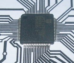
It looks like it can be a powerful thing in good hands.
I decided to test its power, so I needed a development board to use for my experiments. Because I wanted to have a universal board, so I faced a few problems – PCB tracing. My purpose was to make this PCB at home, so I didn’t want to waste time tracing a big board with many tracks. There were two ways of making it: make one big board with the complicated tracing of PCB tracks, or split it into two parts. I’ve chosen the second one. In the first stage, I made an ARM-mini board where I placed the ARM chip and two resonant clock sources: one for core and another for RTC (Real Time Clock). By doing this, I only needed a one-sided PCB. Also, I could reduce the number of pins from 64 to 51. Of course, I sacrificed VDDA ad GNDA pins by connecting them to a digital pat voltage source.
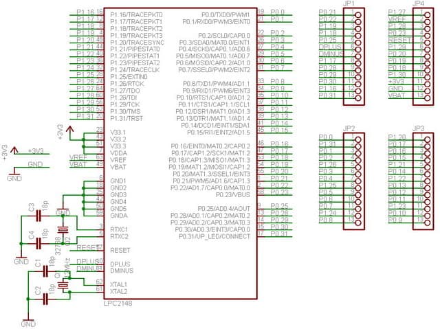
Schematic and PCB are done by using Eagle software. It can be downloaded from https://www.cadsoft.de/. You can use it freely as it is board size limited to 8-10 cm, and make two-layer PCB’s. Also, this tool is available for Windows, Linux, or Mac operation systems. .If you want to make bigger boards, you should purchase them as this is excellent software for intermediate projects.
And here you go – one layer traced PCB. It looks a little bit unprofessional, but it works. I’ve made 0.2mm tracks using UV exposure PCB making technology – you’ll find in other topics.

PCB doesn’t look very good; I think because I used a new UV light expose box, so exposure time, o maybe there wasn’t enough of photo resist development. But as all tracks are OK, I decided to leave it as it is.


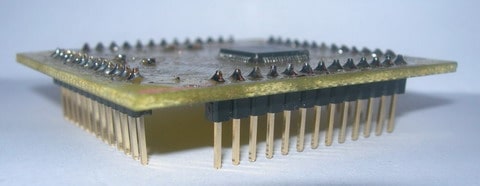
Completed and soldered mini-board. Soldering wasn’t as hard as it seemed so. I used iron, solder, and plenty of flux. Results you can see below.


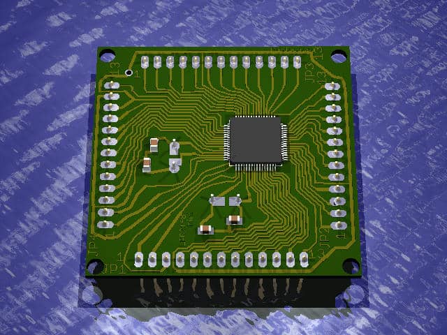
Here you can see how I created an adequate 3D model of my ARM mini with Eagle3D. You can download Eagle3D from https://www.matwei.de. With it, you can create very realistic looking PCB layouts or even animation.
I have also created an eagle library element to use ARMmini for future development boards.
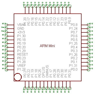
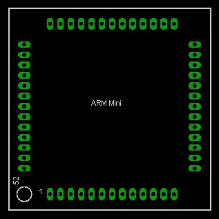
I used this ARMmini board for LPC2148 development board manufacturing.
That’s it for now.
Download PCB files here: ARM Mini Eagle files


Hi
Do you have the lpc2148 library for eagle posted anywhere? I would like a copy.
Best regards
dave
I have added files here: ARM Mini Eagle files
The library of LPC2148 is called Philips_LPC2XXX.lbr
Good luck 😉
May I ask where you got the lpc2148 chip?
I have a board where it is broken and needs to be replaced. I can’t find any supplier to buy online from in Europe.
I opened up the library but the only chips present are the 2194 and the 2294 … is there any chance you would mind posting the library with the 2148, since I haven’t found one on the web.
hi, i m divya , i have just started lpc2148 a month ago…..so pleaz can u say the new models in the market and different standards developed in ARM