After UV-80 was built, there was a thought about automatic PCB Etcher with autonomous Heater and bubble machine. This project is hanging in the prefinished phase, but it does a job. It was used to etch several PCBs. As this etcher is supposed to be used for making PCBs using photosensitive technology, the controller is supposed to control both = the heater of the etching tank and the developer’s heater. As Sensors, there are used AD7416 digital temperature sensors. I decided to publish this small project, as this is not clear when it will be finished. When it is, I will update this article.
There is a little dirty drawing with dimensions:
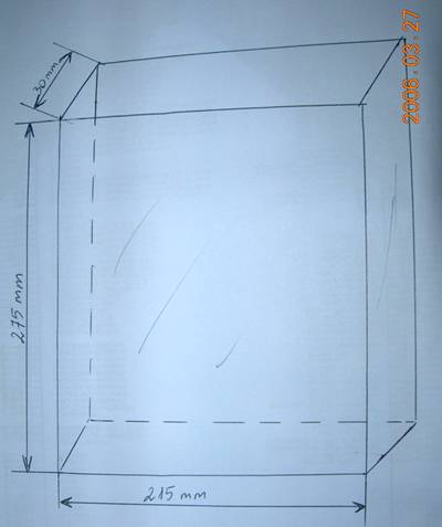
The dimensions are as follows 215x275x30 exterior. The inner volume is smaller as glass is 4mm thick. So the overall volume is less than 1,2 liter. It is an ideal volume to use one bag of ammonium persulphate or 250 grams of FeCl3. The glass plates are glued with aqua silicone. Sides are strengthened with aluminum profiles (not necessary if you have skills of glueing aquariums).
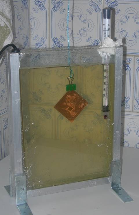
As you can see, it is only manual control 🙂 Thermometer, heater, and tank with an etchant.
The thermometer has scaled with more than 50°C as the solution shouldn’t exceed this value. The heater is used from fish tank 90W:
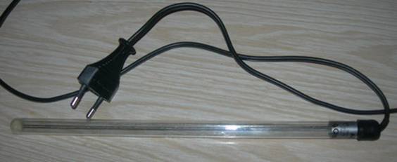
This heater heats the solution to 50 degrees in about half an hour. This is enough time to expose and develop your PCB. If you need to heat water faster – you should use the more powerful heater.
This is nothing to add more to this part. This is working well, but you have to stare and not to overheat the solution.
To make the heater work automatically, we decided to create controller with temperature sensor. Due to problems in assembly, this part is not finished. And there is no bubble machine purchased. A bubble machine is good to speed up etching, and the process is going smoother. As bubble machine we probably will use aquarium bubble pomp.
So what do we have now?
We have a simple circuit on atmega8 to read two temperature sensors and the ability to control two relays to control two heaters.

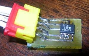
There also are two temperature sensors soldered to be ready to glue to tank glass. I think it should read temperature quite well – maybe little calibration will be needed.
The sensor view:
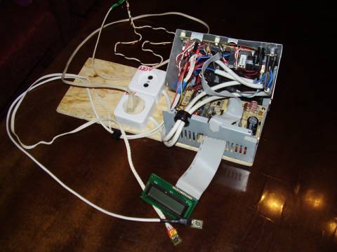
All control boards will be placed in a PC power block – we just have one spare to use as it already has a 5V to power controller and 12V for relays and developer heater. FYI, the developer heater will be a heating wire from some medical equipment. It is powered from 12V and takes about 2 – 3 A (36W). It is enough, as the developer shouldn’t exceed 30 degrees.

And here is the total view of the controller. It still looks messy and not assembled. I hope one day it will be finished
Source code: Source Code


Hi, Im Building UV BOX for PCB exposure really a great project congratulations. Im try to build a PCB etcher and find your project at the same page. About thesource code? Im very interested in your project, could you send me the source code to program microcontroller?
I attached source code to the bottom of article. This is not finished. Here is the link:
https://scienceprog.com/wp-content/uploads/2006/04/Termostatas%2020051216.zip
It would be great the you would send me your project success. I could put few lines about it in my page. Anyway good luck on making your PCB making station 😉
Is this circuit functional?
How do you setup the reference temperature? In the source code or setup manually ???
What do you mean reference temperature? The temperature when relay is turned on and off. Then is is done in code. The temperature is read and compared to reference. If is equal, then relay is turned on/off. There is hysteresis made in source code as well.
Okay!I understand now.
Sorry for the fool questions, Im a physician and electronic is my hobby. Reading the source code the temperature reference is in this interval between 17 and 20 Celsius. May I change to higher levels in the source code? What do you need to finish this project? It is functional if I try to build it now?
The code and circuit is functional. I had bad luck, because I short-circuit the wires, and it burned. But it worked properly, before :). And yes you can change temperature values to any you want.
I hope my one will be finished in near time. Don’t hesitate to as anything you want – there is no fool question you could ask 😉
I really appreciate the information. Thank you so much for the wonderful content you have created! I admire you. Your artical is great! After read it, I think a lot. The content is very exciting and I can almost understand. Please keep going on and continue to add excellent posts. That’s big help for me. You are tops.Great! You have done a terrific job communicating your message. I totally agree with your opinion. Thanks! Your atical is really surprising.