Accessing AVR microcontroller ports with AVR GCC
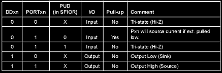
All AVR ports have Read-modify-write functionality when used for general I/O functionality. The direction of each separate port pin can be changed. Each pin buffer has the symmetric capability with the ability to drive and sink source. The pin driver is strong enough to drive LED directly, but it is not recommended to drive even small loads without using proper driver circuit such as transistors. All port pins have internal selectable pull-up resistors. And finally, all pins have protection diodes to both VCC and GND rails. Each port of AVR consists of three registers DDRx, PORTx, and PINx (where x means port letter). DDRx register selects the direction of port pins. If logic one is written to DDRx then the port is configured to be as output. Zero means that the port is configured as an input. If DDRx is written zero and PORTx is written logic “1” then the port is configured as input with an internal pull-up resistor. Otherwise, if PORTx is written to zero, then the port is configured as input, but pins are set to tri-state, and you might need to connect external pull-up resistors. If PORTx is written to logic “1” and DDRx is set…