
Servo motors are so-called “closed feedback” systems. This means that the motor comes with a control circuit inside, which senses if the motor mechanism is in the desired position. If not, it continuously corrects an error until the motor reaches the angle.
Servo motors are widely used in robotics, remote-controlled planes, vehicles, and many other industrial machines. They come in many shapes and sizes, but they all operate in almost the same way.
Usually, servo motors are controlled by a computer, microcontroller, or even a simple timer circuit.
How Servo Motor Control Works
Usually, servo motors are put in the plastic box, but inside there is a whole system: motor itself, gears, and motor driving and control circuit.

The gears reduce motor speed but increase torque. As we mentioned, servos work with a closed feedback loop when the potentiometer is connected to a mechanical shaft and senses the angle of turn. The potentiometer voltage directly indicates the grade of twist. The potentiometer signal goes to a digital controller of the motor, which powers the motor until the potentiometer reaches the desired angle, then the logic circuit shuts the motor.
Standard servos are usually powered by DC voltage from 4.8 to 7.2V.
Servos are designed with a limited rotation angle being 90° or 180° and other. Of course, they can be modified for continuous rotation. Precise rotation and high force are reached thanks to the gear system that makes servos ideal for robotic purposes.
Servo control signals
The Servo motor shaft is positioned with pulse-width modulated (PWM) signals. All servos usually interface with three wires (Power, Ground, and Control). Pulses are sent via control wire. In hobby servos with a rotation angle of 90°, signal width vary between 1 and 2ms. If the pulse is wider, the rotation continues until it reaches mechanical limits.
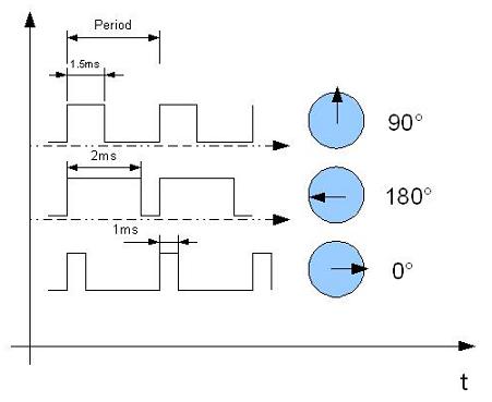
The frequency of the PWM refresh rate usually is in the range of 30 to 60Hz. If the refresh rate is too low, then the servo’s accuracy may be lost as it may look for its position periodically. If speed is too high, then the servo can start chatter. It is essential to select the optimal rate so that that servo motor could lock its position.
The motor circuit adjusts power depending on what is the difference between current and final positions. If this difference is slight, the energy portion given to the motor is low that it wouldn’t overshoot – the motor in this situation is driven slower. If the position difference is significant enough, then the motor is powered to turn at full speed to reach a new position as fast as possible. When the shaft approaches a new position, the movement motor slows down to stop at a specific position at the movement motor’s end. This complicated process lasts for about half a second when the rotation angle is 60°.
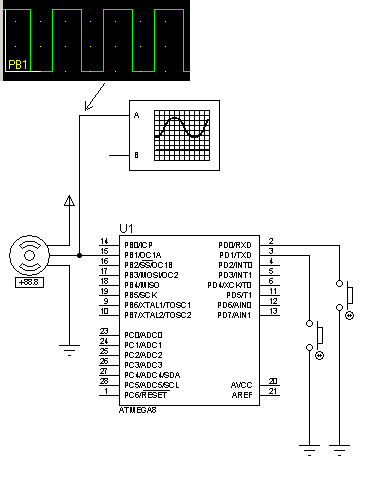
Servo control using Atmega8
Let us write a simple example of servo control using Atmega8 and Timer1 fast PWM. The circuit represents only main parts:
Program code:
//-------------------------
#include <avr\io.h>
int main(void) {
//Port D pins as input
DDRD=0x00;
//Enable internal pull ups
PORTD=0xFF;
//Set PORTB1 pin as output
DDRB=0xFF;
//TOP=ICR1;
//Output compare OC1A 8 bit non inverted PWM
//Clear OC1A on Compare Match, set OC1A at TOP
//Fast PWM
//ICR1=20000 defines 50Hz PWM
ICR1=20000;
TCCR1A|=(0<<COM1A0)|(1<<COM1A1)|(0<<COM1B0)|(0<<COM1B1)|
(0<<FOC1A)|(0<<FOC1B)|(1<<WGM11)|(0<<WGM10);
TCCR1B|=(0<<ICNC1)|(0<<ICES1)|(1<<WGM13)|(1<<WGM12)|
(0<<CS12)|(1<<CS11)|(0<<CS10);
//start timer with prescaler 8
    for (;;) {
if(bit_is_clear(PIND, 0)){
//increase duty cycle
             OCR1A+=10;
loop_until_bit_is_set(PIND, 0);
            }
if(bit_is_clear(PIND, 1)) {
//decease duty cycle
            OCR1A-=10;
loop_until_bit_is_set(PIND, 1);
            }
    }
}
//----------------------------------