
In the previous example, we implemented a simple demo program that reads buttons by continually checking their status in the main program loop. This isn’t an efficient and convenient way to do that. Imagine your application has to do lots of tasks, and in between, you also need to check button status – mission becomes impossible unless you use interrupts. In this part, we briefly introduce to STM32F10x interrupt system and write example code where LEDs and buttons are serviced within interrupts.

ARM Cortex-M3 microcontrollers have an advanced interrupt system that is pretty easily manageable. All interrupts are controlled inside Nested Vectored Interrupt Controller (NVIC), close to the Cortex core, to ensure low latency and robust performance. Main features of NVIC include:
- Interrupt preemption – automatic support for nested interrupts where the higher-level exception may interrupt the lower level that is currently processed. NVIC takes care of saving context to stack. As everything is done in hardware, there is no need for assembler wrappers like we do in other MCUS. All that is needed is to ensure that you won’t run out of stack memory and set the right interrupt priorities;
- Tail chaining – it’s a mechanism allowing to reduce latency if an exception occurs during or just after the current ISR routine. In this case, MCU doesn’t have to do full unstacking that allows entering another pending exception as soon as possible.
- Late arrivals – a feature allowing to overtake current lower priority interrupt, which is in the stacking process stage.
These features are handled automatically, and you don’t have to care much about this – enjoy faster ISR response.
STM Cortex-M3 interrupt system
During microcontroller initialization (when start-up code is run), all exception/interrupt vectors are usually stored at the beginning of flash memory starting from address 0x00000004. Address 0x00000000 is used to store the initial stack pointer value.

As you can see in the table, the first 15 interrupts are generated within the cortex core, while others down the list are interrupts caused by peripherals like pins, timers, ADC, DMA, etc. STM32F103ZET6 NVIC can handle up to 60 maskable interrupt channels plus 16 lines of core interrupt. Each interrupt (except the first three: Reset, NMI, Hard fault) can have 16 priority levels set with 4 bits in an 8-bit priority level register. The lower number indicates a higher priority. The higher priority may preempt lower priority automatically. Priority bits may be split into two groups called Preemptive priority and sub-priority. This doesn’t change much but helps organize priorities so that the same preemptive level priorities could be arranged into sub-priorities to decide which should be handled first. All this is done with the same 4- bits what leads to a total number of 16.

The whole procedure of enabling interrupts consists of the following steps:
- Select the interrupt channel in the NVIC module;
- Set preemptive priority;
- Set sub-priority;
- Enable interrupt for a particular line.
You have to take care of the interrupt service routine where your code will be performed when an interrupt occurs.
EXTI and pin mapping
External interrupts from microcontroller pins aren’t traced directly to NVIC as you’d expect. STM32 provides a flexible mechanism that allows the mapping of different pins to the same channel. This gives lots of freedom to decide on which pin to generate an interrupt on which channel. So external interrupts are managed through External Interrupt/event Controller (EXTI). EXTI can be set to rise event on rising, falling, or both edges. 19 lines in EXTI are associated with mapped pins and other sources. 16 lines are dedicated to port pins, each line for a separate PIN like this:

The other three lines are devoted to RTC alarm interrupt, power voltage detection (PVD), and a USB wakeup event. Then these lines are traced to the NVIC controller in the following manner:
- EXTI0 to EXTI4 are traced directly to NVIC as separate channels;
- EXTI5 to EXTI9 are grouped to a single NVIC channel (EXTI5_9);
- EXTI10 to EXTI15 are grouped to a single NVIC channel (EXTI10_15);
- RTC alarm, PVD, and USB wakeup are also traced as single separate channels in NVIC.
Some practical examples
Having this information, we can start building our code. In our development board buttons are connected as follows:
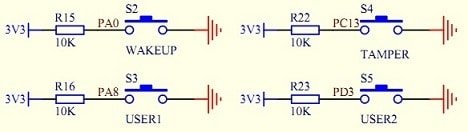
Each of them accidentally (or maybe not) fall into positions where each of them can be mapped to different EXTI lines that allow having dedicated NVIC channels. This way we will be able to write separate handlers for each button:
- EXTI0 line for WAKEUP button (EXTI0_IRQHandler);
- EXTI3 line for USER2 button (EXTI3_IRQHandler);
- EXTI9 line for USER1 button (EXTI9_5_IRQHandler;
- EXTI13 line for TAMPER button (EXTI15_10_IRQHandler;
We are going to write a simple routine where each button will toggle related LED. To set up buttons for generating interrupts we write the following ButtonInitEXTI() function:
void ButtonsInitEXTI(void)
{
	//enable AFIO clock
	RCC_APB2PeriphClockCmd(RCC_APB2Periph_AFIO,  ENABLE);
	EXTI_InitTypeDef EXTI_InitStructure;
	//NVIC structure to set up NVIC controller
	NVIC_InitTypeDef NVIC_InitStructure;
	//GPIO structure used to initialize Button pins
	//Connect EXTI Lines to Button Pins
	GPIO_EXTILineConfig(BWAKEUPPORTSOURCE, BWAKEUPPINSOURCE);
	GPIO_EXTILineConfig(BTAMPERPORTSOURCE, BTAMPERPINSOURCE);
	GPIO_EXTILineConfig(BUSER1PORTSOURCE, BUSER1PINSOURCE);
	GPIO_EXTILineConfig(BUSER2PORTSOURCE, BUSER2PINSOURCE);
	//select EXTI line0
	EXTI_InitStructure.EXTI_Line = EXTI_Line0;
	//select interrupt mode
	EXTI_InitStructure.EXTI_Mode = EXTI_Mode_Interrupt;
	//generate interrupt on rising edge
	EXTI_InitStructure.EXTI_Trigger = EXTI_Trigger_Falling;
	//enable EXTI line
	EXTI_InitStructure.EXTI_LineCmd = ENABLE;
	//send values to registers
	EXTI_Init(&EXTI_InitStructure);
	//select EXTI line13
	EXTI_InitStructure.EXTI_Line = EXTI_Line13;
	EXTI_Init(&EXTI_InitStructure);
	EXTI_InitStructure.EXTI_Line = EXTI_Line3;
	EXTI_Init(&EXTI_InitStructure);
	EXTI_InitStructure.EXTI_Line = EXTI_Line8;
	EXTI_Init(&EXTI_InitStructure);
	//disable AFIO clock
	RCC_APB2PeriphClockCmd(RCC_APB2Periph_AFIO,  DISABLE);
	//configure NVIC
	//select NVIC channel to configure
	NVIC_InitStructure.NVIC_IRQChannel = EXTI0_IRQn;
	//set priority to lowest
	NVIC_InitStructure.NVIC_IRQChannelPreemptionPriority = 0x0F;
	//set subpriority to lowest
	NVIC_InitStructure.NVIC_IRQChannelSubPriority = 0x0F;
	//enable IRQ channel
	NVIC_InitStructure.NVIC_IRQChannelCmd = ENABLE;
	//update NVIC registers
	NVIC_Init(&NVIC_InitStructure);
	//select NVIC channel to configure
	NVIC_InitStructure.NVIC_IRQChannel = EXTI3_IRQn;
	NVIC_Init(&NVIC_InitStructure);
	NVIC_InitStructure.NVIC_IRQChannel = EXTI15_10_IRQn;
	NVIC_Init(&NVIC_InitStructure);
	NVIC_InitStructure.NVIC_IRQChannel = EXTI9_5_IRQn;
	NVIC_Init(&NVIC_InitStructure);
}
It may seem a bit complicated, but indeed this is simple when you know what you’re doing. Just a quick overview of what’s done. First of all, when modifying/using some peripheral, don’t forget to enable the bus clock for or otherwise, you’ll end up wondering why it’s not working when settings seem to be OK. So are going to be used as other functions. This is why we need to enable the AFIO bus clock. We simply map button pins to adequate EXTI lines with GPIO_EXTILineConfig() function, which sets proper bits in AFIO->EXTICR registers. Then we select Interrupt mode for EXTI lines (there can be software events also). Generate interrupts on the falling edge and with these settings enable the current EXTI line. This has to be done with each line.
Once EXTi lines are configured, we can disable the AFIO bus clock and proceed to NVIC settings. Here we are setting priorities and sub-priorities for each channel and enabling each of them one by one. This is it. Now we can implement interrupt handlers that we are going to place in the separate source file (stm32f10x_it.c). Here we implement codes:
void EXTI0_IRQHandler(void)
{
	//Check if EXTI_Line0 is asserted
	if(EXTI_GetITStatus(EXTI_Line0) != RESET)
	{
		LEDToggle(1);
	}
	//we need to clear line pending bit manually
    EXTI_ClearITPendingBit(EXTI_Line0);
}
And so on for all channels. Within handler, it is good practice to check if the current EXTI line is asserted. Then we can do our business as toggle LED. And before leaving the EXTI handler, it is essential to reset the EXTI line as it stays set until manually cleared. If not, this line will generate chain constantly interrupts as NVIC takes this as pending interrupt all the time.
Finally, we can write our main code which is nothing much left:
//STM32F103ZET6 Buttons Test
#include "stm32f10x.h"
#include "leds.h"
#include "buttons.h"
#include "stm32f10x_it.h"

int main(void)
{
  //init leds
  LEDsInit();
  //init buttons t ogenerate interrupts
  ButtonsInitEXTI();
  //start sys tick timer that also generates interrupts
  SysTick_Config(15000000);
  while (1)
  {
	//your tasks
  }
}
All we need is to implement LED pins, Initialize buttons by calling ButtonsInitEXT() function, and that’s it. To show another exciting feature of the Cortex microcontroller, I also enabled the SysTick timer, which generates SysTick interrupts every second.
void SysTick_Handler(void)
{
	LEDToggle(5);
}
Interrupt handler toggles LED5.