Adding self power down functionality to your devices
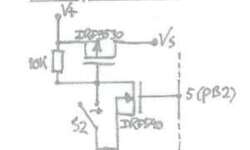
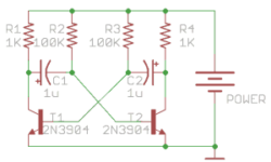
The power-down feature is convenient on battery-operated devices. For instance, most of the multimeters already have this feature allowing them to self turn off when there is no activity for some time. Check out this simple solution, which uses a pair of FETs and resistors. It was initially made for the Atmega328 project because the author didn’t want to bother with AVR power-down modes. Instead, he used this simple circuit. It can be used to turn the device on with the switch. This is where the P-FET part plays a role and turn off with N-FET. Turn Off signal wire comes from AVR pin market as 5. While the device is powered, N-FET has to be on with a high gate signal. When the N-FET gate signal goes low device turns itself off. This can be used on any device where possible to get such signal conditions. Or use in microcontroller circuit by adding some delay count after inactivity.