Driving Graphical LCD with STM32F103ZET6
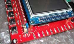
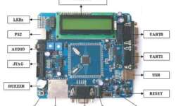
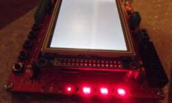
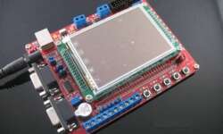
STM32F103ZET6 board comes with 3.2 inches graphical LCD which features an ILI9320 controller. Equipped LCD is capable of displaying 252144 colors when driven in 18-bit mode. We are going to run it in 16-bit mode, so we are limiting it to 65K colors. LCD driver is based on the existing code found on the internet, originally developed for the STM3210E board. Only minor modifications were needed, like assigning the proper control pins.