RS232 interface standard overview
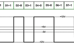
This is a pretty old standard but still widely used in embedded systems. Using the RS232 interface standard, the data is sent bit by bit. Usually, first comes LSB. The receiver receives data by knowing the position of each data piece and delay. To ensure the quality of data transmission, we need to control the start of transmission. The acknowledgment procedure does this. Let’s take the asymmetrical type of interface RS232-C. The transmitter sends RTC (request to send) signal to the receiver. On the other hand, the receiver detects this signal, finishes the previous operation, and then sends to receiver CTS (clear to send) signal, which means that receiver is ready to accept data. Without CTS transmitter cannot start data transmission. Note: In the RS232 interface, logical “1” corresponds to voltages from -3V to -12V, and logical “0” corresponds to voltages from +3V to +12V. The logical level in the interval -3V to +3V is undefined.