Sometimes we need to project a simple filter with particular characteristics. We usually take calculations with ideal parameters and don’t look at tolerances of them. Let us see how simple filter output depends on its elements tolerances.
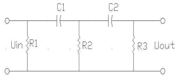
For this let’s choose simple filter circuit:

We are going to calculate the filter response characteristics. The bandpass frequency is taken on 0.707 level of response. We will see how this frequency depends on the electronic element tolerances. I will model elements with tolerances ±10%.
I calculate transfer function using quadrupole network method:

Network matrix:

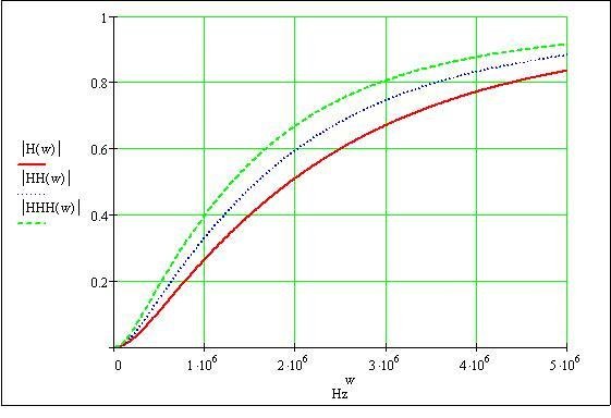
And here is a transfer characteristic:

Bellow you see marginal characteristics, when element values are +10% and -10%

HH(w) – ideal parameters 0 deviation, HHH(w) – deviation -10%, o H(w) – +10%.
We see that characteristic varies in a pretty wide range. If we need to calculate bandpass frequency, we need to calculate average and dispersion.
Average:

Dispersion:

Calculated data
| Frequency | Hz | Average | Dispersion |
| Least | 994177 | 1226203 | 1.486E+10 |
| Optimal | 1202954 | ||
| Maximal | 1485129 |
If element parameters deviation limits are ±10%, then the frequency can vary from 994177Hz to 1485129Hz the range is 490952Hz. As you see, this is quite a little Accuracy.
So if you need better tolerance, you need to select proper elements. And remember that not all electronic elements have the same impact on overall tolerance. To evaluate this, optimization is needed.


