In general, there are two ways to control DC motor speed: by varying supply voltage and pulse width modulation (PWM). The first control method is not convenient, especially in digital systems. It requires analog circuitry, and so on. The second motor speed control method is very convenient for digital systems because all control is made using only digital signals.
As you already know, PWM (Pulse Width Modulation) is all about switching speed and pulse width (duty cycle). Duty cycle is the ratio of signal time ON/T. T is the period of the signal.

In the above diagram, you see two signals. The first duty cycle is about t1/T=1/3, and another’s duty cycle would be about t2/T=2/3. And notice the period of signals are the same.
If we apply these signals to the switching transistor, we would get control over effective voltage across the motor:
Vefective=(tON/T)*Vcc;
Where tON-signal on time over one period T.
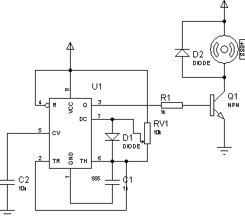
In this way, you can control motor speed using microcontrollers PWM output, or if you need, you may use a simple control motor PWM schematic constructed using IC555 timer circuit:

Without going too deep into 555 timer’s performance analysis, I can mention that the duty cycle can be changed using potentiometer RV1. The signal period won’t change as the overall resistance between Vcc and 555 pins 6 does not change.


Hi Scienceprog, hope you can reply to this question to my e-mail. I have seen the same concept of developing a PWM source with 555 timers. However all the ones I have seen involved using a 556 (555 dual timer). It eventually occured to me that only one 555 timer would be needed for simple motor control. Could you please explain why other schematics use the dual timer design?
I guess that by using two 555 timers you have better control of generation of PMW, because one IC is dedicated to generated the frequency and another is to select duty cycle. The main feature of using two 555 timers is that you can have much wider range of frequencies while using one 555 timer gives you limited option to adjust frequency.
Thanks sienceprog.
what is the type of transistor?
There is NPN transistor which depends on motor power. For instance you can use 2N3055.
It is better to use n-channel MOSFET transistor for instance IRFD024 or IRFZ46N which is more effective than general purpose transistor.
hello sir,
I am a TY Btech Elex student. i need a C code for PWM control of DC motor controller using ATmega16 and IC L293D IC. Can u pls help me out?
Awaiting your reply
Why do we use a mosfet in this circuit