VGA to X-Y-Z scope converter
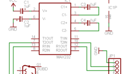
This is a fun project I found on Jon’s antique radios web-page. He has managed to convert the VGA output signal from PC to X Y X oscilloscope signal. Converting the VGA RGB signal to a synchronized oscilloscope input signal is pretty easy because VGA has two sync signals separate from RGB signals. Look at pin-out of VGA cable: Sync signals make things much easier as there is no need for additional sync signal generators – thus circuit becomes pretty simple without any programmable components: