It is convenient to drive dot LED matrix displays using IC drivers of 5×7 dot LED matrices like MAX6952 and MAX6953. These two IC’s differ only by data interfaces: SPI for MAX6952 and I2C for MAX6953. In this article, you will see how these driver IC’s can be controlled by a computer using an LPT port.
The program provided here works with almost all Windows versions: 95, 98, 98SE, ME, NT, 2000, and XP. The printer ports that can be used are LPT1 and LPT2. The program is called MAX6952, and it is programmed by using Visual Basic 5. To start this program, you will need a few standard VB run time libraries: MSVBVM50.DLL. The program uses a freeware driver of parallel port: DriverLINXTDLPortIO.DLL, responsible for hardware I/O in win32.dll and is not accessible by standard VB. Windows NT and Windows 2000/XP require drivers too. It is DLPortIO.SYS. Both drivers are owned by Scientific Software Tools, Inc. DriverLINXT is a registered trademark of Scientific Software Tools, Inc.
First of all, installation on win98. Download file MAX6952-95.exe (793kB). This is a self-extracting archive that contains ReadMe.txt, ReadMeSST.txt, MAX6952.EXE, DLPortIO.DLL, and MSVBVM50.DLL. By default install directory is C: MAX6952. File MSVBVM50.DLL can be removed if this library is already registered on your PC.
To install the program on win NT, win2000/XP, download file MAX6952-NT.EXE(2.378kB). This is a self-extracting archive that contains: ReadMe.txt, ReadMeSST.txt, MAX6952.EXE, PORT95NT.EXE, and MSVBVM50.DLL. By default install directory is C: MAX6952. Program PORT95NT.EXE registers libraries DLPortIO.DLL and driver DLPortIO.SYS, which is part of DriverLINX. File PORT95NT.EXE can be deleted after installation. This procedure may be used for win95 and win98.
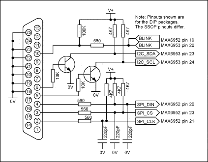
Now software part is set up, let’s move to the hardware part. The program above uses 3 and 8 output lines of LPT port for SPI interface simulation and additional 2 lines for I2C interface simulation. One line of the port is used for reading blink status. It is possible to control several IC MAX6952 (up to 16 in series) at one time. You can choose LPT1 or LPT2 within the program interface. Port may be working in standard, ECP, or RPP mode. Connection circuit bellow:

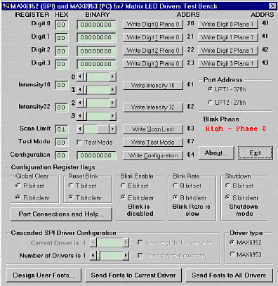
The program window after startup is below. The initial state of registers of MAX6952 and MAX6953 are seen here after power-up—select driver type: MAX6952 – SPI or MAX6953- I2C.

When are working in SPI mode, it is possible to control 16 drivers. Drivers are connected in cascade: DOUT of the first driver IC is connected to DIN of the second driver IC of MAX6952 and so on.
The number of drivers is defined by the slider Number of Drivers. When setting up more than one driver – Enable global driver write and Enable auto-increment check-boxes enable. When Enable global driver write is unchecked then during command execution writing is done only to the driver which is selected by slider Current Driver. If check-box Enable global driver write is checked then the same data is written to all drivers. If Enable auto-increment is checked then the driver counter increases automatically. This allows sending different data to all drivers of the Dot LED matrix in series.
After the program is started SPI interface can be tested with the function Test Stream , which is located in PORT Connections and Help…. Test Stream utility continuously sends NOP code to drivers to test them.
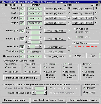
When working in I2C mode, the program also allows the controlling of up to 16 drivers MAX6953. Firs driver has the address of 1010000x following drivers have addresses up to 1011111x. Another control is the same as for SPI mode. Testing is also done by function Test Stream:

Now comes the fun part – Design User Fonts this button calls procedure that allows creating and storing User Symbols displayed in dot LED matrix. By default, there are pre-built few symbols that are stored in the MAX6952_fonts.txt file:
The interface is very intuitive. Symbols that you create can be saved to file or sent to drivers of the dot LED matrix.
Data file format is as follows:
- Font 0Data 00011100Data 00011100Data 00011100Data 00011100Data 00011100
- Font 1Data 01111111Data 01111111Data 00111110Data 00011100Data 00001000
- Font 2Data 00000000Data 00000000Data 01111111Data 00000000Data 00000000…
Font xx shows font number where xx can be from 0 to 23;
Dataxxxxxxxx – one row of 8-bit data for dot LED matrix (up to 7 rows for one symbol);
Data is saved fro MSB to LSB which describe symbol.


Great article. Could you do me a favour, and show the whole schematic? I’d very appreciate. Thanks in advance.
I agree with Flip, I was also lookking for a schematic. Thanks anyway, nice article.
I have been designing with the MAX6952 and they work
fine, have you been able to scroll Text using them
Thanks,
Phil
pmj32p@yahoo.com
Hello phil I looked into the data sheet of 6953 could not understnd pls do me favour if I want to display my name wht should be done after the start condition and address byte
i too interested in the schematic part of this design. Mr.Filip and Dr.Amer have you got schematic.
can any any one please send me the schematic to me.
thanks in advance.
With Regards,
S.Balaji
Highly interested in schematic, too.
Could you share it with us?
Thanks, David.
still waiting for the schematic….
Please share if any one has…
sribalajitech [] gmail []com
i too interested in the schematic part of this design. Mr.Filip and Dr.Amer have you got schematic.
can any any one please send me the schematic to me.
thanks in advance.
With Regards,
S.Balaji