Sensing Sound Wave with microcontroller
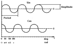
A sound wave can be sensed by using a sound sensor. If you are designing a robot, sometimes it is useful to enable sensing of sound. Then you can program your robot to follow your voice commands. In some cases, sound wave sensors are used as collision sensors. A sound wave sensor is a microphone. The microphone is a device that converts sound pressure into electric signals. Let’s see how sound waves can be sensed. As we already know, the sound is a complex signal which consists of multiple different frequency waves. One sound wave can be represented as sin or cos signal: When many of such waves are summed (s called harmonics), we can represent any analog signal- any shape and any frequency.

Continue reading

Prototype board types

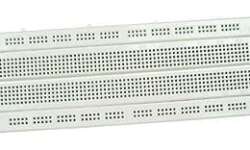
If you are starting to take an interest in electronics, this is a good thing to know what type of prototyping boards can be used. There can be four types of prototype boards: Solderless breadboard- where connections are made by using jumpers;

Continue reading

USB powered power amplifier for your PC

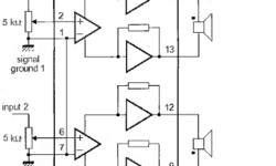
I faced this article when I was looking for a simple solution to increase the output of my PC’s integrated sound card. The sound level of it decreased, so I can’t normally listen to my headphones. So this article is about how to increase your PC sound card’s power by using a minimal amount of parts and a USB power supply. This might be a good solution for all of those who have a PC with an integrated sound card into the motherboard. The main problem is that the outputs of such sound cards are for active acoustic systems; this means that speakers must have a power amplifier built-in. If you decide to connect headphones sometimes, it might not be enough to provide the required sound level. If you are an electronics amateur, you can solve this very easily. You may build your simple power amplifier by using well known Philips operational amplifiers. Let’s say we use the TDA7053 amplifier. The TDA7053 is an integrated class-B stereo power amplifier in a 16-lead dual-in-line (DIL) plastic package, which requires a minimal amount of external parts. This is a straightforward solution for easy, quick, and quality design. One of the board solutions…

Continue reading

Radio Frequency Identification RFID

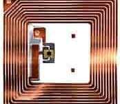
There are two types of RFID devices: Active and Passive. Active devices have a power source built-in, which supplies the transmitter. The transmitter is triggered by sending the signal to an RFID device. These devices have their own code and can transmit signals in desired time intervals. Active RFID devices are good in defining locations of objects or sending some information about a particular place (RFID-based location determination). Active RFID devices use high frequencies (455MHz, 2,45GHz, or 5,8GHz) – working range about 20 – 100 meters. The most common are passive RFID. They don’t need a power source. Passive RFID devices are low frequency(124 – 135kHz – low) and high(13,56MHz – 960KHz – high; 2,45GHz – UHF). The working principle of low and high-frequency devices differ. Simultaneously, low-frequency readers generate a magnetic field that induces a current in the RFID device antenna. The chip inside the RFID device modifies this magnetic field, which is reread by the reader. The working distance of such a device is about 35cm.

Continue reading

What is surface mounting?

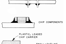
Simply talking surface mounting is a soldering technology where the component is soldered directly to a series of solder pads called a footprint. It is different soldering technology from through-hole, where component leads are inserted into holes of the board. The footprint is a series of pads that conform to the lead layout of packages of surface mount devices (SMD). Surface mounting has several advantages over through-hole technology. First of all the board become much smaller. So smaller boards and more dense placement of elements reduce costs. Because of higher placement density, traces between components becomes shorter. It lowers parasitic inductance and capacitance.

Continue reading

Shelling The Intel 8-bit Hex File Format

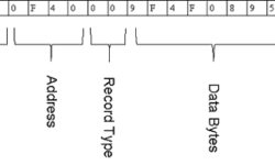
Intel 8-bit Hex File Format is the most common hex file format used globally, as far as I know. There is also Motorola Hex file format and maybe others. Creating applications with AVR-GCC, we usually select ihex output file format what means Intel hex file format. Let’s go through it and see what’s inside. It is simple as 6 and 6 (six and six) because each Hex file line consists of six parts. And there can be 6 record types in the hex file. Lets go through all six parts of each line:

Continue reading

RS232 interface standard overview

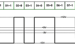
This is a pretty old standard but still widely used in embedded systems. Using the RS232 interface standard, the data is sent bit by bit. Usually, first comes LSB. The receiver receives data by knowing the position of each data piece and delay. To ensure the quality of data transmission, we need to control the start of transmission. The acknowledgment procedure does this. Let’s take the asymmetrical type of interface RS232-C. The transmitter sends RTC (request to send) signal to the receiver. On the other hand, the receiver detects this signal, finishes the previous operation, and then sends to receiver CTS (clear to send) signal, which means that receiver is ready to accept data. Without CTS transmitter cannot start data transmission. Note: In the RS232 interface, logical “1” corresponds to voltages from -3V to -12V, and logical “0” corresponds to voltages from +3V to +12V. The logical level in the interval -3V to +3V is undefined.

Continue reading

Why use watchdog variable timer

Most of the embedded microcontrollers contain watchdog timers. The watchdog variable timer is literally watchdog. The watchdog timer continuously inspects the program flow. Basically, if the microcontroller program hangs, then the watchdog timer resets it and brings the embedded system back to life. The idea is elementary. Let’s say, you know, that your program has to be executed during 20ms. And you know that the worst-case scenario is 30ms. Then you set the watchdog variable timer connected to the highest priority interrupt RESET. Once the Watchdog timer is triggered, the timer counts up to the time you set, and then it resets the MCU. The only way to avoid resetting is to send a command to the watchdog timer to start counting. Technically watchdog variable timer is nothing more than a retriggerable one-shot multivibrator.

Continue reading

Always read newest datasheets

Reading of datasheets is or should be an important part of designing electronic devices. Reading datasheets is necessary for writing device requirements, planning budget, and selecting suitable components. Datasheets of each component may be found in manufacturers website. Once you’ve selected a suitable component, be sure that you read the datasheet and understand everything in it. Otherwise, you may miss some critical parts that could ruin all your plans. It is better to find errors before you start designing than after. Another important issue is that always check for newest datasheets and errata – datasheet bug lists. It is not good practice to use your old datasheets from your hard drive archive or other places. These datasheets may contain bugs. Just download the newest microcontroller or other semiconductor datasheet and compare to yours downloaded let’s say a year ago. Errata’s and datasheet changes are usually listed at the end of the datasheet. You may look at this and find out what would you miss with old datasheets. The electric characteristics maybe are the same, but there may be configuration bugs or even discovered bugs in hardware and proposed workarounds to avoid them. So be critical and don’t rely blindly on…

Continue reading

How to read electronic circuits

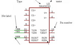
In electronic circuit drawings, there are two types of objects: component symbols and nets. Nets represent wires connecting the components – which represent physical devices. In the example below, we see component type MAX3232. U2 is a reference label of a component. Electronic component usually has pins. Pins always have their numbers starting from 1. Pins also have their names. They are usually written inside component blocks like C1+. For this particular component, we used the U2 label. U (or IC) label applies to all semiconductors. But you know that resistors usually are labeled as R1, R3. Capacitors C1, C2, Diodes – D1, D2, Transistors Q1, Q2, Crystals – X1, X2, X3, Jumpers J1, J2, J3, Inductors L1, L2.

Continue reading