A sound wave can be sensed by using a sound sensor. If you are designing a robot, sometimes it is useful to enable sensing of sound. Then you can program your robot to follow your voice commands. In some cases, sound wave sensors are used as collision sensors. A sound wave sensor is a microphone. The microphone is a device that converts sound pressure into electric signals.
Let’s see how sound waves can be sensed. As we already know, the sound is a complex signal which consists of multiple different frequency waves. One sound wave can be represented as sin or cos signal:

When many of such waves are summed (s called harmonics), we can represent any analog signal- any shape and any frequency.
X(t)=A*sin(2πt/T)=A*sin(2πft),
Where A – Amplitude, T – Period, f=1/T – frequency, t- time. This is a function of the above sine signal. I am not going too deep into details of trigonometric functions. You can find them in many math or physics book.
Let’s see how square impulses can be made of a few different frequencies, phase, and amplitude sine waves.

We can see in the illustration that by adding multiple harmonics, we can get the desired signals. The more harmonics we add – the more accurate signal we get. The frequency of the first harmonic defines the frequency of the signal. Mathematic formulas you can find anywhere. I just wanted to show an idea, what signals are made of. Logically thinking if we can combine signal by adding multiple sines or cosines, then there is the ability to split the signal into separate waves. For these filters are used. If we want to extract the first harmonics, we can use the low-frequency filter. The lof frequency filter characteristics are shown in the following illustration:

Cut off frequency of the filter is at level 0.707. This means that signal is reduced 1.414 times, which is 3dB.
Simple low frequency filter may be Butterwort active filter:

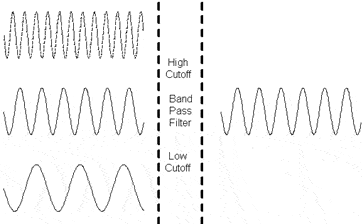
There are many types of filters, low pass, high pass, bandpass, band stop. They can be analog or digital and so on. How they can be used to recognize some voice commands in embedded systems. Of course, if you are using general-purpose microcontrollers then it is quite hard to implement the digital filter. One solution can be to use an analog filter like bandpass. If we know, that command is going to be a sound wave (1kHz) then you use a bandpass filter to select only 1kHz sound wave from environmental noise.

Using a microcontroller, you can detect filtered signals, and the microcontroller can react with some action. Let’s say you want your robot to be able to recognize 3 commands. Then you can use three bandpass filters like 1kHz, 1.5kHz, and 2kHz. To send accurate sound waves, use whistles with the mentioned frequencies. This is a simple method. If you want a more reliable system, you should use some coding of sound commands and so on.


