K-Type Thermocouples reviewed

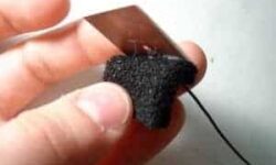
A thermocouple is a sensor that generates an electrical potential related to the temperature. The sensor’s operating principle is based on the fact that any electrical junction between two different metals generates an electrical potential that depends on the temperature and the metals used. The principle applies equally well if three metals are used. In that case, there are two junctions in series and the net potential results from the series addition of the two individual potentials. For example, if a copper iron junction is in series with an iron-tin junction, the net potential is the same as for a copper-tin junction. However, that is only true if both junctions are at the same temperature. The K-Type thermocouple is usually made of Chromel (+) and Alumel(-). The voltage generated from this sensor is 4mV/100°C. The max temperature that can thermocouple withstand is 1000°C without any damage.

Continue reading

Gauss-Zeidel optimization routines

This is the simplest optimization routine. Using this algorithm, optimization parameters are changed separately in each step. Only one parameter can be changed in one step while others are held as constants. Xk+1=Xk+ΔXk , k=0,1,2,… ΔXk step of parameter Xk. The parameter is changed until function growth is noticed, and then the next parameter follows, and so on. After the cycle with all parameters is completed, the step is changed to half its value and repeats. Optimal point searching ends when there is no function increase, and the last point is held as an optimal point. First function optimization example Its plot: Using the MATLAB script, we get the results below. In each picture, the start coordinates are different.

Continue reading

Impulse signal distortion in the transmission line

Today most electronic equipment consists of signal generators and processing units. These units are connected with transmission lines. These lines have a big influence on signal distortions. On these lines depends transmission lines stability. Let’s see how transmission lines affect transmitted signals. (G- signal generator; Za– output impedance; I- signal receiver Zb– input impedance; L- transmission line length; Z0– Line impedance. When line is tuned and without losses then input voltage: Ub(t) = ZbE(t-t)/(Za + Zb) E(t)- generators signal amplitude; t- signal delay in line. t =l/v ; l- line lenght; v- signal speed. If the line is not tuned up, then there are distortions in line because of reflections inline: If signal E(t) is step function: Then signal in line exit in discrete time moments will be: U(0) = p; U(t) = p*(1+pb) U(2t) = p*(1+pb+pa*pb) U(3t) = p*(1+pb+pa*pb+pa*pb^2); U(4t) = p*(1+pb+pa*pb+pa*pb^2+pa^2*pb^2); U(5t) = p*(1+pb+pa*pb+pa*pb^2+pa^2*pb^2+pa^2*pb^3) … where Depending on reflectance coefficients and their signs distortions can differentiate or integrate: A real model using MathCAD was implemented to see how the signal looks on exit depending on parameters. Below you see used algorithm structure used in modeling: Part 2: One of results using trapezoid signal: In exit we get distorted…

Continue reading

Life-giving to Atmega8

I have got two ATmega microcontrollers from my friend. He stated that they are burned and can be thrown into the garbage. He also mentioned that they stopped responding after they were programmed. So I asked him to give those to me to try them. I had in my mind that this is a result of a bad usage of security bits. There is always confusion in these bits because of writing ‘0’ values program security bits and unprogrammed with ‘1’. I didn’t really expect to make them working again as my friend did quite rude experiments with them. What can I say – he was right by saying they are burned. But I guess some of you will like to see what I was doing to recover them. I decided that he unprogrammed all four security bits ( CKSEL0, CKSEL1, CKSEL2, CKSEL3 )by writing ‘1’ to them. This situation means that Atmega8 has to be clocked from an external clock signal. I was supposed to program those bits to work ATmega normally with a quartz resonator.

Continue reading

Filter output dependency on tolerance of elements

Sometimes we need to project a simple filter with particular characteristics. We usually take calculations with ideal parameters and don’t look at tolerances of them. Let us see how simple filter output depends on its elements tolerances. For this let’s choose simple filter circuit: We are going to calculate the filter response characteristics. The bandpass frequency is taken on 0.707 level of response. We will see how this frequency depends on the electronic element tolerances. I will model elements with tolerances ±10%.

Continue reading

DullRazor – digital skin hair shaver

DullRazor uses image processing techniques to analyze and segments skin areas with dark hair. This program removes dark hair form images and makes skin lesion images clean to further processing. From: To: Many skin images contain various numbers of hairs. Other skin segmentation programs may mislead because of hairs – especially dark ones. One solution can be shaving skin before taking pictures of it. But shaving of skin adds more time to processing, and this is uncomfortable and, in some cases, unaesthetic.  Hence, a software approach for dark, thick hair removal from skin images are needed.

Continue reading

Skin Cancer causing factors

Substance Where this can be found How to avoid Arsenic Pesticides, wood preservatives, alloy additive non-ferrous metals. Use protective clothing when working with arsenic substances Creosote Wood preservative Use protective clothing when working with  creosote substances Ionizing radiation Ionizing radiation is specific industrial sterilization sources Limit exposure if possible. Wear a dosimeter while working with radiation. Sunlight Summer, and when on a sun holiday. Avoid strong sunlight, especially at midday. Wear protective clothing to protect your skin. Cover exposed skin with sunscreen of factor 15 or higher. Tar Coal tar Use protective clothing Glutaraldehyde Glutaraldehyde is used as a disinfectant. It is also can be found in X-ray films. Use protective clothing when dealing with glutaraldehyde. Work only in well-ventilated areas. Soot Black particles of carbon, produced by incomplete combustion of coal, oil, wood, or other fuels Use protective clothing Pitch It is made by the destructive distillation of wood or coal tar Use protective clothing Asphalt Sticky, black and highly viscous liquid or semi-solid that is present in most crude petroleum and in some natural deposits Use protective clothing Paraffin wax   A member of the alkenes series Use Gloves Smoking   Smoking cigarettes increase your risk of cell carcinoma…

Continue reading

Z axis accelerometer MMA1220D from Freescale

MMA1220D is Z-axis MEMS accelerometer -8g – +8g. This sensor has a capacitive sensor. The output signal is passed through a 4 poles low pass filter. It also has an internal self-test capability. The main features:Integral signal conditioning;Linear output;Ratiometric performance;4th order Bessel Filter to preserve pulse shape integrity;Calibrated self-test;Detection of low voltage also clock monitor and EPROM Parity check status;Can survive big shocks. Where can it be used? It can be the perfect tool for Vibration monitoring, control, bearing monitor, PC HDD protection, mouse and joystick, virtual reality, sports diagnostics.The datasheet can be found here:https://www.freescale.comI decided to run a sample test for this sensor. For this, I just made a simple board where I soldered this sensor with the SOIC16 package. According to the datasheet, I put an RC filter on sensor output to minimize clock noise. There is a schematic: And traced PCB: I used SMD parts as it will be easier to glue another side of the board to any surface in the future. First test drive on oscilloscope: Later I will do some tests by connecting this sensor to MCU.Bellow, I attached the Protel library of the MMA1220D sensor and my project files. It might be you…

Continue reading

PCB Etcher

After UV-80 was built, there was a thought about automatic PCB Etcher with autonomous Heater and bubble machine. This project is hanging in the prefinished phase, but it does a job. It was used to etch several PCBs. As this etcher is supposed to be used for making PCBs using photosensitive technology, the controller is supposed to control both = the heater of the etching tank and the developer’s heater. As Sensors, there are used AD7416 digital temperature sensors. I decided to publish this small project, as this is not clear when it will be finished. When it is, I will update this article. There is a little dirty drawing with dimensions: The dimensions are as follows 215x275x30 exterior. The inner volume is smaller as glass is 4mm thick. So the overall volume is less than 1,2 liter. It is an ideal volume to use one bag of ammonium persulphate or 250 grams of FeCl3. The glass plates are glued with aqua silicone. Sides are strengthened with aluminum profiles (not necessary if you have skills of glueing aquariums).

Continue reading

Ultraviolet light source UV-80 for PCB exposure

One of the more advanced PCB manufacturing methods is exposing laminate copper boards covered by a photo resistive layer through the mask. Using UV light in manufacturing PCB’s has many benefits according to other methods: you can get thin tracks like 0.2mm. You couldn’t do this using other home techniques like laser printers or hand artwork; another advantage is that this method gives a clean image – smooth edges of PCB tracks. Little bit effort and you can compare results to commercial products. And of course, the third benefit is speed and multiple replications of your boards by using the same mask. This article is described in the manufacturing of an automatic ultraviolet light source exposure box. Parts for UV box Case with organic glassPanelUV lamps ballasts and startersController Case Case is made of 5mm wood board wired with screws. Making a control panel The Control panel consists of two parts: Power control and Automatic control.A POWER switch is used to turn the on/off the power of the UV box. Green LED indicates the ON. MANUAL/AUTOMATIC switch is used to power l the UV lamps manually or automatically. Switches UPSIDE and UNDERSIDE are used to enable upper and lower lamps…

Continue reading