Ultraviolet light source UV-80 for PCB exposure

One of the more advanced PCB manufacturing methods is exposing laminate copper boards covered by a photo resistive layer through the mask. Using UV light in manufacturing PCB’s has many benefits according to other methods: you can get thin tracks like 0.2mm. You couldn’t do this using other home techniques like laser printers or hand artwork; another advantage is that this method gives a clean image – smooth edges of PCB tracks. Little bit effort and you can compare results to commercial products. And of course, the third benefit is speed and multiple replications of your boards by using the same mask. This article is described in the manufacturing of an automatic ultraviolet light source exposure box. Parts for UV box Case with organic glassPanelUV lamps ballasts and startersController Case Case is made of 5mm wood board wired with screws. Making a control panel The Control panel consists of two parts: Power control and Automatic control.A POWER switch is used to turn the on/off the power of the UV box. Green LED indicates the ON. MANUAL/AUTOMATIC switch is used to power l the UV lamps manually or automatically. Switches UPSIDE and UNDERSIDE are used to enable upper and lower lamps…

Continue reading

Healthy skin reflectance model

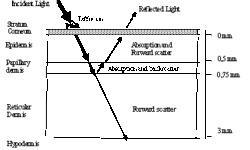
This pilot study is intended to investigate possibilities of skin nevus imaging using digital still image camera. The main objective is to develop a dermatology image interpretation method, which enables the looking on the skin lesions and nevus from the optical background of skin colouration. Kubelka-Munk calculation method for light transport and reflection from multilayered, complex media is applied to model light reflection spectra of skin. Calculation of model shows that red, green, blue and infrared colours lighting is satisfactory to access distribution of comparative estimates of the following skin parameters: volume fraction of melanin in the epidermal layer, the volume fraction of haemoglobin in the dermal layer, presence of dermal melanin and thickness of the papillary layer. Performance of image processing method on fourteen samples of images of common melanocytic nevi, dysplasia melanocytic nevi, Spitz nevus, thrombotic hemangioma and surrounding healthy skin were made. Skin spectral properties Understanding how light interacts with skin can assist in designing physics-based dermatological image processing. The key is understanding how light interacts with skin tissue. The skin consists of different layers with different spectral properties. Fig 1. Skin model and its physical view When incident light is applied to skin layer, it is…

Continue reading

Review on skin lesion imaging, analysis and automatic classification

The goal of any imaging methodology used in dermatology is to diagnose melanoma in the early stages because it depends on treatment effectiveness. Investigations show that early diagnosis is more than 90% curable and late is less than 50% [1]. The diagnosis and successful treatment are often supplemented with permanent monitoring of suspicious skin lesions. The doctor’s diagnosis is reliable, but this procedure takes lots of time, effort. These routines can be automated. It could save lots of doctor’s time and could help to diagnose more accurately. Besides using computerized means, there is an excellent opportunity to store information with diagnostic information to use it for further investigations or create new methods of diagnosis. Skin lesion imaging methods We found that there are several various imaging methods of skin lesions [2]. The simplest skin visualization method is photography. This method gives only the top layer of the skin image. To get a deeper layer image, there is oil immersion used. It reduces reflections of the surface and brightens the image of the epidermis – the second skin layer.

Continue reading

Discrete systems in series and parallel

Discrete systems in series We have two discrete systems, and their impulse responses are h1(n) and h2(n). Then when these discrete systems are connected in series, then overall impulse response: Where: As you noticed there were changing made: This is nothing more than convolution of impulse responses of both discrete systems: Discrete systems in parallel If we have two discrete systems connected in parallel: As we see, there is a simple sum of output queues of each discrete system. So we can assume, that the overall impulse response is the sum of systems connected in parallel:

Continue reading

Impulse Response of discrete system

Impulse signal can be represented as:d[n] = 1, if n=0d[n] = 0, otherwiseit can also be written like d=[1,0,0,0,…] Impulse Response The impulse response h(n) is the response of filter L() at time n to unit impulse occurring at time 0.h(n)=L(d(n))Let’s see how a discrete system can be described when impulse response is known We know that: In the linear system this can be written as follows: Because h(n-k)=L(d(n-k))Then: What do we get? Its impulse response can describe a linear system. The last expression is called convolution. This is the heart of DSP Filtering.To write this sum in the more convenient matter is assumed that: Matlab example Matlab example: As you can see if the input queue has N samples, impulse response has M after convolution there will be total N+M-1 samples.

Continue reading

What is a linear system?

A discrete system is nothing more than an algorithm, where input is transformed into output. The output is transformed by operator L(), which describes the discrete system.Let’s see the few most common operators of discrete systems. Delay This means that output queue is delayed by on sample. Multiplication This operator takes each sample of input queue and multiplies by constant a. Sum operator Takes two or more sample queues and adds them in the output. Assuming we can say, that the system is linear if input sum reaction is equal to sum of inputs reactions: The system has stable parameters if:y(n-k)=L(x(n-k)), this means that output delay should be the same as the input.It is obvious that delay, multiply, and sum operators are linear and have stable parameters. We will need them for further lessons.

Continue reading

Understanding of discrete signals

Discrete signals can be generated by software or obtained from the real-world through ADC. Discrete signals are sampled from analog signals. So you get samples in fixed time intervals. The discrete signal is a sequence of numbers. The element number n of the sequence is marked as x(n). The most common number rows: Unit sample sequence You can describe it in Matlab like

Continue reading

Physiological system modeling

Most physical and chemical experiments can be described with a finite number of rules. In physiological processes, everything can be tied to the laws of nature. A good model can be a guideline for new experiments. Usually, the model and experiment have an iterative connection. To understand how to investigate any material, there is a model needed (block 1). First, we need an abstract understanding of what we are investigating (block 2). Abstracts are transformed into mathematical models (block 3). There we can use formulas and solve them using the computer. The results you get shows, what experiments have to be done, and what to expect from them. This loop system is resistive to irregularities in the mathematical model. In other words, this is the purifier of experiments and models.

Continue reading

CMOS and TTL compliance

There was a time when all IC’s were only TTL type. They were marked as 74LS or 74ALS. But then there came CMOS types of semiconductors. They are usually marked CDxx. And lately, there appeared combined semiconductors that are compliant with both types. They usually are marked as 74HC or 74HCT.TTL is faster than CMOS, but they sink more power. They are powered from a 5V source. To diminish the power consumption, the CMOS was developed. They can work with supplied voltages in the range of 3 to 15V. The main disadvantage is that they are static sensitive. So you always have to be grounded when working with CMOS.Now both types of semiconductors are widely used. Sometimes there is a dilemma to connect TTL to CMOS. You cannot connect TTL directly to CMOS as there are different supply voltages. So it would help if you had some compliance circuit. The simplest can be bipolar transistor cascade. Just remember that such a cascade inverts the signal, so you might need to put an inverter in front of CMOS. Another reminder – never leave TTL or CMOS free pins hanging. Jus connect them through a resistor to VCC or GND.

Continue reading

Skin lesion boundary tracing algorithm

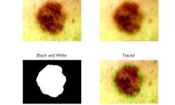
I found Matlab to be a convenient tool that easily traces the boundaries of objects in a picture. So I adopted it to skin lesions. This can be used to automatically detect skin irregularities and calculate lesion properties like the asymmetry of shape, or border irregularities, which can help detect melanoma. There are numerous investigations done, so I only put a few examples of how it looks. I will give you my source code so that you can try it on your own. Look at my results: 1) And it also finds the center of mass:

Continue reading