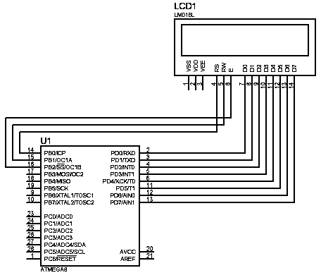
Simulate KS0108 graphical LCD with Proteus simulator

Today it is common practice to use various circuit and microcontroller simulators for developing programs. Using simulators, you have several benefits comparing to real prototype boards. You don’t have to connect any hardware to test a piece of code; also, you don’t have to be in the same place when working. You can have simulator software on your Laptop and work where ever you want. Of course, you can see more parameters within the simulator like register values, memory, signals in a convenient form. So controlling graphical LCD on simulator software like Proteus is an easy task.

Continue reading

Reliable soldering with fluxes

Reliable soldering can be achieved by soldering clean surfaces. Usually, surfaces are cleaned with abrasives and solvents, but after the surface is cleaned surface immediately oxides, especially when heated. During oxidation, the surface is covered by thin oxide film, which prevents solder from contacting metal. This is why flux is used in the soldering process. To remove/deoxidize, surface flux must be applied during soldering. Flux chemically removes surface oxide when heated and makes a good metal to solder contact. There are several categories of soldering fluxes: Acid Flux (or commonly known fluxes: Zinc chloride, hydrochloric, ammoniac); Organic Flux; Rosin Flux. Each flux has its own specifics and may be used for different soldering technologies.

Continue reading

What are MEMS

Today MEMS is a common acronym among engineers. Therm MEMS stood for micro-electro-mechanical system and was started to use in 1980sin USA. MEMS are called systems because they are sensors and contain electronic circuitry inside which conditions sensor signal. Simply speaking, MEMS is usually a chip device that integrates mechanical elements, sensors, actuators, and electronics. Most interesting and important partis mechanical. Miniaturizing the mechanical parts using micro-machining technology when selectively parts are etched away, it became possible to create mechanical structures on silicon base and electronic devices. MEMS devices are used everywhere today, including automotive, industrial even computer hard drives with MEMS sensors for shock protection. The ability to integrate mechanical sensors inside the chip made it possible to design compact accelerometers, gyroscopes, pressure sensors, sensors with integrated RF, and many more. Also, technology enables the integration of more than one sensor inside the chip. One example may be 3-axis accelerometers. A major producer of inertial MEMS is Analog Devices, which produce accelerometers and gyroscopes.

Continue reading

Controlling graphical 128×64 LCD based on KS0108

HQM1286404 is a pretty old graphical LCD module, but it is still popular. KS0108 driver controls this LCD. LCD backlight color is yellow-green. I think this is an excellent choice for many projects where graphical information is needed for several reasons – you can find libraries around the internet to start working in just a few minutes. Several tools can also be used to generate character arrays and graphics. The hardest thing for me was to find the correct wiring as the datasheet I have was for the next PCB revision (HQM1286405) as mine are HQM1286404, so don’t be mistaken as I did. Here is the correct pin-out of LCD:

Continue reading

What is worst-case timing analysis

Many of your PC hardware people have probably faced similar problems when assembling a computer from different parts, and it seemed to work properly. But under some circumstances system crashes without any known reason. Even in my practice, I had a sound-card that works well, but time at the time, it just crashes, and then the computer hangs. Of course, I can blame drivers or operating systems, but there is another probability that there can some timing failures occur. Many complex productions around us may have many undefined failures due to a lack of timing worst-case analysis. Failures may occur due to power supply fluctuations, thermal changes, or other conditions. Worst-case analysis encounters all available information of condition variations that can affect the performance of components. The worst-case analysis shows if electronic design meets specifications under variable conditions like temperature, voltage, or other variables. Only detailed analysis can prove if the design will work reliably under all operating conditions. It is proved that it is much better to design reliable hardware than fix the problems later. In many ways, the worst-case analysis may be implemented in various manufacturing phases automatically. By including several simple tests may save lots of money…

Continue reading

Chemical effects of electricity

Electronics depend on chemistry more than you can imagine. To generate electricity, there are many methods used; one of them is chemical. Remember batteries, where electricity is generated because of chemical reactions inside the cell. In conductors like liquids and gases, electricity is carried not by electrons in solid constructions(copper, aluminum, etc.) but by ions – molecules with electric charges. Even non-distilled water contains enough ions to be conductive. Let’s go through several chemical effects of electricity. Electrolysis Electrolysis decomposes the liquid compound by passing an electric current through a liquid called an electrolyte(saltwater, copper sulfate, sulphuric acid). Electrolysis is used very widely in the industry, like electroplating metals, refining copper, and extraction of aluminum from ore. To make electrolysis happen, two conductors used cathode(-) and anode(-).

Continue reading

Circular buffers in DSP processors

I will not analyze what DSP processors are different from regular microcontrollers as many differences allow boosting performance in many specific tasks like filtering, FFT, etc. One thing is obvious that DSP processors have to perform mathematical calculations rapidly enough to get predictive results. The better result we want – the more processing power we need. We know that MCU is performing two main tasks: data manipulation and mathematical operations. But the fact is that it has to be done really fast. General-purpose microcontrollers aren’t optimized to perform these tasks effectively as microcontroller has to as much universal as possible to fit in many areas. In other words, flexibility reduces performance. DSP processors are more specialized microprocessors optimized for tas that they usually do – multiplication and addition. Let’s take the most common DSP routine FIR digital filter implementation. It takes several samples of signal x[] and produces output signal y[], modified by multiplying appropriate samples by coefficients an. y[n] = a0x[n]+a1x[n-1]+…+akx[n-k]

Continue reading

Automated electronic CAD systems overview

More and more design operations become automated. These changes give many benefits like effectiveness, minimal errors, and less routine operations to designers. Modern electronic equipment requires scrupulous planning as devices shrink to minimal sizes, operation power increases, and it fit its external design requirement. So designing is a very complex task where without smart CAD software would be almost impossible to do. When designing a new electronic device, you have to deal with several necessary areas to make the device a reliable and attractive device. All of these areas usually are done on a particular CAD system. The most common CAD-based electronic specific task are: Mixed Analog-digital device modeling; Programmable Logic modeling and synthesis; HF circuits and electromagnetic modeling; Functional modeling; PCB Design; Thermal modeling; Chip topology modeling. Each of these modeling and designing processes requires different skills and knowledge. Let’s go through each to see their specifics and what CAD systems are used to automate related tasks.

Continue reading

AVR analog comparator and avr-gcc example

An Analog comparator is a pretty simple peripheral, but it can give big benefits. Comparator module is included in all Mega series of AVR microcontrollers. Simply speaking, Comparator allows comparing voltage values applied to two pins of microcontrollers. The comparison results are a logical level, which can be read by the program(ACO- Analog Comparator Output bit). There is also the ability to generate an interrupt, which depends on the comparator resulting level. And more- timer T1 can capture this level what allows measuring the signal length of analog signals. To use pins as comparator inputs, they must be prepared and configured as input(DDRx=0), and pull-up resistors must be disconnected (PORTx=0). In some models like Atmega48x/88x/168x, Atmega165x, Atmega325x,3250x,645x/6450x, and Atmega640x/128x/1281x/2560x/2561x, there is the ability to disconnect digital buffers of AIN0 and AIN1 pins that allows the use of these pins only for analog signal input – this minimizes overall power consumption.

Continue reading

What is DebugWire interface

Debug wire is an interface that enables debugging AVR microcontrollers by using one wire. All new AVR microcontrollers with less than 16kByte memory have a built-in one-wire bidirectional debugging interface that allows debugging devices in real-time. Like the JTAG interface, DebugWIRE can handle full execution and program flow control. It also supports an unlimited number of breakpoints, adjusting memory contents. The good thing is that interface doesn’t require additional pins as only the RESET pin is used for debugging purposes.

Continue reading