AVR controlled signal generator-skeleton board

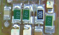
This is continuing of thread AVR controlled signal generator. In earlier post 1 layer PCB prototype, I described a little about making this small project’s PCB. Now a few words about soldering and making the first test run. >This is my PCB board’s bottom. During soldering, I discovered one mistake – ISP headers pin MISO and MOSI were swapped. So I had to do some fixes (the green wire). Another small problem I discovered was that I couldn’t find 20k SMD resistors for my R-2R leader. For this DAC R-2R leader, I need 10k and 20k resistors to make DAC work properly. So I decided to make “fun” with my Board and soldered 10k SMD resistors in series to gain 20k:

Continue reading

From analog to digital signal filtering

A signal filter is an electrical equipment that attenuates the unwanted signal characteristic wave. Filters can be analog or digital. An analog filter processes analog signals. They are mainly arranged with capacitors and resistors. Digital signal filters process digital signals which are quantized. Digital filters are arranged with solid-state components to process the signals. L’s start from analog filters. An Analog filter is a circuit that filters unwanted frequencies. Filtering is done by choosing the circuit transfer function. Simplest analog low pass filter: The current in RC circuit can be calculated as follows:

Continue reading

AVR controlled signal generator design considerations

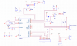
A signal generator is a second must-have tool after oscilloscope while working with electronics designs. I don’t have any signal generators, so I decided to make one. This is gone be a simple AVR-controlled signal generator. I’ve chosen the Atmega8 microcontroller as this is the simplest one of Atmega’s series microcontrollers. It has 8kB flash memory. This is an initial post of the project. I have only designed a schematic and PCB board. I’ll be adding project progress in further posts. A little bit about AVR controlled signal generator. This is going to be a stand-alone generator coated in a 100x60x35mm metal box, the one I’ve found in my drawer. It will be powered by a 9V battery (through a 7805 voltage regulator). Controlling will be done with a series of buttons on the box side. And the information will be viewed on the 2×16 LCD screen on top of the box.

Continue reading

Atman AVR kick start

Atman AVR is an integrated c/C++ compiler IDE for Atmel AVR microcontrollers. AtmanAvr C development environment includes ProjectWizard, CodeWizard, Workspace, Output, Text editor, Binary editor, Debugger. The compiler itself is a GCC compiler for AVR. The only thing that makes it commercial is the integrated environment: ProjectWizard – lets you customize a project through series dialogs, and then it generates initial code automatically; CodeWizard – helps in programming routine tasks like creating new modules, adding functions navigating; Advanced workspace where you can find File View, Class View, and I/O View, and many more. If you would like to try this IDE, you may download AtmanAvr C IDE from the manufacturer’s site https://www.atmanecl.com. Bellow is an Atman AVR kick start guide with some screenshots: Create new project File->New: In the Project Name enter the name of your project. Also, select where your project will be located. From tab Projects select one type of projects:

Continue reading

Tradeoff between DC motors and stepper motors

103-546-5342 steper motor

This is a small comparison made between three types of motors: DC motors and stepper motors. Let’s see what their cons and pros are: Stepper motors don’t require feedback to determine position. The microcontroller determines the position by sending pulses to stepper motor; When the load is too high to the stepper motor, then it may stall, and there is no way to report this to the microcontroller; DC motors with feedback can report stalls on high loads or other conditions; Stepper motor has no brushes – there is no EMI; Stepper motor may produce full torque – this enables them to hold the rotor in the desired position; DC motors deliver more torque at higher speeds than stepper motors; Stepper motors can produce low speed without loss of torque. Dc motors lose torque at low speed because of low current;

Continue reading

I2C EPROM programmer

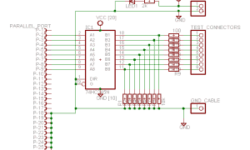
Sometimes you need to program I2C EEPROM chips and don want to invest any bucks in it. Then you should consider the I2C EPROM programmer originally designed by Claudio Lanconelli. This is very easy to build and use circuit but it supports 24C01, 24C02, 24C04, 24C08, 24C16 24C32, 24C64, 24C65, 24C128, 24C256, 24C512 I²C Bus EEPROM, auto-detects 24XX EEPROM capacity For the I2C EPROM programmer, you need to download PonyProg programmer software from www.lancos.com. Choose “Easy I2CBus” from the Options – Setup menu and the parallel checkbox on WindowsNT/2000. You have to select “AVR ISP I/O.”

Continue reading

Serial Peripheral Interface – SPI Bus overview

Serial Peripheral Interface is a simple interface that enables communicating microcontroller and peripheral chips or intercommunicating between two or more microcontrollers. Serial Peripheral Interface Bus, sometimes called four-wire interface, may be used to interface such chips or devices like LCD, sensors, memories, ADC, RTC. The range of usage is huge. SPI Bus uses the synchronous protocol, where transmitting and receiving is guided by a clock signal generated by the master microcontroller. SPI interface allows connecting several SPI devices while master selects each of them with CS (Chip Select) signal – (Underline means that active is LOW). SPI bus consists of four signal wires: Master Out Slave In (MOSI), Master In Slave Out (MISO), Serial Clock (SCLK or SCK) Chip Select (CS) for the peripheral. Some microcontrollers have a dedicated chip select for SPI interfacing called Slave Select (SS). The master generates a MOSI signal – the recipient is Slave. MOSI may also be labeled as SI or SDI. Slaves generate MISO signals. In some chips, you might find labels SO or SDO. SCLK or SCK are generated by master to synchronize data transfers. CS (SS) signal is also generated by master to select slave chip or device. Data transfer is…

Continue reading

7805 voltage regulator for your design

This is the most common voltage regulator that is still used in embedded designs. The LM7805 voltage regulator is a linear regulator made by several manufacturers like Fairchild or ST Microelectronics. They can come in several types of packages. For output current up to 1A, there may be two types of packages: TO-220 (vertical) and D-PAK (horizontal). With a proper heat sink, these LM78xx types can handle even more than 1A current. They also have Thermal overload protection, Short circuit protection.

Continue reading