Flashing STM32 using J-Flash ARM
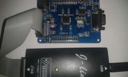
Last time, we covered the topic of flashing STM32 microcontrollers using the bootloader, which is the most comfortable and cheapest way of loading programs into MCU memory. But this isn’t the only way of doing this. The firmware can also be downloaded using the JTAG adapter, which is also used for debugging. This time we are not digging into debugging but staying only with programming. J-Link software You can download the latest J-Link software from the Segger Download page. You will be asked for an adapter serial number which can be found on the backside of the J-Link adapter.

Continue reading

Microcontroller based apps for android mobile phones

Smartphone devices are as valuable as there are some useful apps there. So I started wondering if there are electronics/microcontroller-related apps that could be useful in daily work. Let’s see what we can find in an in-app store. First of all, we are interested in free apps. Search on AVR microcontrollers gave me coupe results: AVR Fuse Calculator and Using Atmega128 apps. Let’s see what they are capable of.

Continue reading

Adding self power down functionality to your devices

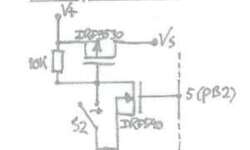
The power-down feature is convenient on battery-operated devices. For instance, most of the multimeters already have this feature allowing them to self turn off when there is no activity for some time. Check out this simple solution, which uses a pair of FETs and resistors. It was initially made for the Atmega328 project because the author didn’t want to bother with AVR power-down modes. Instead, he used this simple circuit. It can be used to turn the device on with the switch. This is where the P-FET part plays a role and turn off with N-FET. Turn Off signal wire comes from AVR pin market as 5. While the device is powered, N-FET has to be on with a high gate signal. When the N-FET gate signal goes low device turns itself off. This can be used on any device where possible to get such signal conditions. Or use in microcontroller circuit by adding some delay count after inactivity.

Continue reading

Interrupt driven AVR USART communication

avr usart

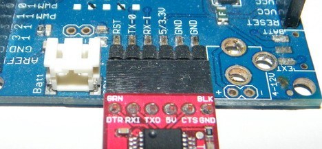
Simple USART routines are not always practical because waiting transmitting buffer to be ready in a simple loop occupies processor resources. If we do not know when data will be received, we are just wasting resources inside the waiting loop. Another issue arises when multiple data bytes have to be sent/received. In this case, we have to write complex code to deal with the data flow. Since the microcontroller’s specialty is interrupting, it is better to use them to handle communications, improving overall performance and energy saving. Instead of continuously checking if there new data received in the UDR register or checking if send buffer is free, lets us write a more effective USAR communication code with a guardian, which would wake the MCU if it has received a byte via USART. On the other hand, Interrupt mode allows performing other tasks at total capacity while waiting for USART interrupt. Let us implement interrupt driven AVR USART communication example.

Continue reading

Project demo on STM32F103RBT6 using GCC

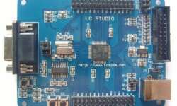
STM32F103R board is a simple and easy development board to learn STM32 microcontroller programming. Its heart is an STM32F103RBT6 ARM Cortex-M3 microcontroller with 128K of Flash and 20K of SRAM memory. It can be clocked at the maximum 72MHz frequency and considered a medium-density performance line microcontroller. Other features include USB, CAN, seven timers, 2ADCs, and nine communication interfaces. The Development board has several excellent features to get started. First of all, it has an RS232 interface for communicating and accessing the bootloader. There also is a USB 2.0 full-speed interface connector that also can work as the power supply. Next is a JTAG connector to program microcontroller using tools like a J-Link adapter. Two pushbuttons and two programmable LEDs are hardwired to MCU pins alongside all I/Os connectors.

Continue reading

Harvesting energy with home made solar thermal collector

The nearest star from Earth is Sun. And it emits a massive amount of energy, which is free. No surprise, many people try to get most of it at a minimal cost. Photovoltaic solar panels still have low efficiency and yet are quite expensive. Every day we hear how their effectiveness is increased by introducing new technologies. Anyway, solar panels require direct Sun, which in some regions doesn’t appear very often. So how can we get this energy with almost no initial cost? The easiest way to do so is to build a solar thermal collector. You can find lots of high efficient commercial collectors. They look great and, at some level, works in the wintertime when Sun shines. I decided to go simpler. I need hot water only in spring, summer, and fall. In the wintertime, I burn wood to heat the house and so water. I usually boiled water using an electric boiler in the summertime, which generates excellent bills at the end of the month. No more… So I started this project, which is still in the testing phase. But seems to work fine. Let’s go through the build process to make a simple solar collector using…

Continue reading

Avoid smoke with power protection circuit

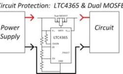
When designing an electronic device, you want to make sure that it won’t go in smoke under unexpected circumstances. You never know what may go wrong during the device’s lifetime, primarily if it is powered from mains. The small circuit between your battery and device may protect it from mistakes like reverse power polarity. His lists start with a simple series diode, which is cheap but may help protect from reverse polarity. Like any other, it has a downside – voltage drop (0.7V) that may be a pain for low voltage devices.

Continue reading

AVR GCC LCD library allows connecting pins in any order

Probably some of you are struggling in finding a proper LCD driver that would work on any circuit. I just wanted to point out that I found some time to improve my current LCD library to support a mixed pin connection case. Earlier, you had to connect LCD in a pretty strict way where pins had to be aligned and attached to a single AVR port. Sometimes this can’t be done for various reasons – you want to use those pins for other alternative functions, or you want to trace your PCB better, etc. In this updated version of the library, there are two more modes added: LCD_4BIT_M and LCD_8BIT_M that allow controlling LCDs either in 4 or 8-bit mode but with any pin connection layout. So data pins and control pins can be connected to any PIN and any port. A couple of examples should give some clue on how to start using it. If you used this library for some project, you only need to modify the header file while the project source code can remain the same.

Continue reading

Modeling of analog part for DDS3 signal generator

When building an AVR DDS2 signal generator, there were many discussions about signal conditioning in the analog part of the device. The first argument was that LM358 wasn’t the best choice for this purpose. Another one pointed to the sine wave that wasn’t smooth enough. As you can see, there are some dents on it. Other waveforms also are distorted, especially when higher voltages are selected. This asks for a better analog part. Some people suggested replacing LM358 with OPA2134, but it seems to be quite an expensive choice. In my opinion, low noise, a general-purpose op-amp can be great too. I’m going to give a try to Texas Instruments TL074 low noise op-amp. It is low power, high slew rate (13V/us) IC – almost five times faster than LM358 and for the same reasonable price.

Continue reading

Multivibrator – back to basics

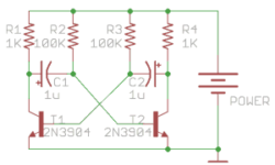
Multivibrator circuit is one of the first projects you start learning electronics. It is a beautiful circuit widely used for educational purposes and even in end projects as waveform generators. Lots of hobbyists grab a microcontroller/Arduino to blink LEDs. But using basic circuits like multivibrator may be cheaper, faster, and even fun. [Ray] decided to go through multivibrator theory and explain its working in detail step by step. The circuit itself consists of two transistors, two capacitors, and four resistors. When powered, the circuit generates a square wave signal that can be used to flash LEDs or clock other circuits. You will get an intuition on what causes multivibrator to develop generate. Formulas allow calculating resistor and capacitor values for a particular frequency. If you are a starter in electronics, build one on a breadboard and do some experiments, why not start with Christmas lights.

Continue reading