Simulating MOSFET based bidirectional 3.3V to 5V logic level shifter
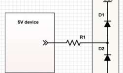
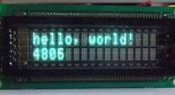
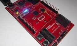
Different logic levels are a common problem in various circuits. For instance, Arduino boards come powered from 5V or 3.3V. Raspberry Pi is powered at 3.3V, and it accepts and generates 3.3V signals on its GPIO. This is fine until you need to connect the 5V peripheral to a 3.3V device. This can be a simple LCD. Of course, you can get 3.3V LCDs, but this is not always the solution. Sometimes it is handy to build a voltage level converter. It can be a special buffer IC like SN74LVCC3245A. These work great as bidirectional voltage translators. But in many cases, there is no need for another IC in your circuit. Hobbyists like to go with simpler solutions. The simplest way is to use resistors, where signal levels differ. The fact is that in most cases, devices have clamping diodes on the inputs that are meant to protect a further circuit from over-voltages. For instance, clamping diode inside a 3.3v device will try to limit the input voltage to 3.3V. This is why a series resistor necessary to limit the current flowing through the diode. Using resistors doesn’t guarantee safe operation. First of all, you must be sure that the…