
Today electronics is shifting to SMT (Surface Mount Technology) or SMD (Surface Mount Devices) area. DIP domination has left behind.

They won’t vanish from the electronics industries as they are many areas and will be successfully used. But as electronic circuit complexity grows, demand for PCB miniaturization increases, there is no other way to use SMD technology to achieve these goals.
Electronic hobbyists noticed that it is harder to find some particular electronic elements in DIP-packages. Many microcontroller types are released only in SMT packages like Atmega128– QFP64, LPC2000 microcontroller series in the LQFP package series. I don’t talk about bigger IC like AVR32 or FPGA, where BGA packages come with 672 connection balls.
This situation pushes us all to another level of prototyping. Many electronic designers and hobbyists are using SMT for quite a long time as they see its benefits. The rest of through-hole technology lovers have to accept and manage the SMT. There is nothing difficult up to some level. Probably you have tried to solder SMD resistor or some SOIC IC. It may look difficult at first glance, but some patience and you will master this.
Let’s go through some popular SMD devices and see how they look and how to deal with them.
SMD resistors come in several package types and sizes. Each size is described as a four-digit number. The first two digits indicate the length and the last two – width (in 0.01 or 10 mils units). For instance:
- 0603: means 0.06″x0.03″, or 60×30 mils, or 1.6×0.8mm
- 0805: means 0.08″x0.05″, or 80×50 mils, or 2.1×1.4mm
- 1206: means 0.12″x0.06″, or 120×60 mils or 3.2×1.6mm

SMD capacitors from 1pF to 1uF come in the same sizes as SMD resistors: 0603 to 1206. Usually, they are ceramic capacitors.

Other types of capacitors are tantalum SMD capacitors. They come from 1uF, and they are polarized (positive side indicate by bar sign). Their sizes are indicated by letters from A to E:
| Case | L x W x H (mm) |
| A | 3.2×1.6×1.6 |
| B | 3.5×2.8×1.9 |
| C | 6.0×3.2×2.5 |
| D | 7.3×4.3×2.8 |
| E | 7.3×6.0x3.6 |
Following picture helps to indicate tantalum capacitors and other types:

1. Tantalum; 2. Tantalum; 3. Electrolytic Capacitor; 4. Electrolytic Capacitor; 5. 0805 Ceramic; 6. 1206 Ceramic; 7. 1210 Ceramic; 8. High Q Porcelain RF; 9. Variable Trimmer; and 1/4 Watt leaded resistor as reference SMD transistors mostly come in two popular packages SOT-23 and SOT-223:
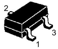
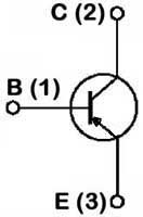
Integrated circuits can be in various packages:
Dual in line: SOIC; TSOP; SSOP; TSSOP; VSOP.
Quad in line: PLCC; QFP; LQFP; PQFP; CQFP; TQFP; QFN; PQFN.
Grid arrays: BGA; LFBGA; CGA; CCGA; μBGA; LLP.
Non packaged devices: COB; COF; COG; MLP; MQFP.

There are various soldering techniques of SMD chips. The simplest one is using regular solder iron better with a temperature regulator to maintain a constant temperature. Just use a lot of flux to avoid solder bridges between pins and make quality soldering joints.
For bigger ICs, it is better to use hot air solder or even a heat oven. Do not afraid to experiment.
A relief to find a page like this for a novice in the hardware industry. Thanks!
info is ver informative. good luck
The helpful information. Thanks.