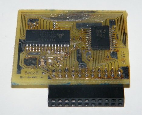
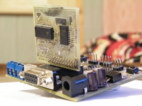
Atmega128 is equipped with internal 4Kbytes of SRAM memory. Is it enough? Well, it depends on what project it’s going to hold. If your project must deal with loads of data or run more extensive RTOS code, you will run out of RAM pretty soon. Atmega128 microcontroller has an external memory interface built-in, which allows expansion of RAM up to 64 Kbytes. With that, you could do much more. I used the Piconomic Atmega128 development board to test things out, which has an XMEM interface header brought out. All we need is to make an XMEM expansion board with some SRAM memory.

I’ve chosen a standard 8Kx8 (8Kbytes) memory chip from Alliance Memory Inc. I could use 64Kx8, but this is what I had at the moment. To drive the memory chip, I’ve used a 74HC573 non-inverting latch. As you may know, the latch is used for pins that share the same pins for address and data buses. To access SRAM contents, we need to select a 16-bit address pointing to an 8-bit data cell in the chip. As we are using an 8Kx8 memory chip, we are going to use only 13Address lines. The microcontroller has dedicated pins for that:
AD[0..7] (PORTA pins) – multiplexed data and low order address pins;
A[8..15] (PORTC pins) – high order address pins;
ALE (PG2 pin) – address latch enable;
RD (PG1 pin) – inverted read strobe;
WR(PG0 pin) – inverted write strobe.
Microcontroller board runs at 7.3728MHz, so standard 74HC series latch timing characteristics are exceptional – no unique delays are needed. Here is the schematic;

Once the board is ready, it is time to test it attached to AT128mega board.

To test if the external memory board works, we will write a simple routine that tests if the microcontroller can allocate memory heaps, write to, and read from then. First of all, we have to set up the AVRStudio project. If you are going to use automated make file generation, you need to add external RAM options, so the compiler would know what address range to allocate for RAM. To do so, open AVRStudio Configuration options and in custom options, add a line to Linker Options:
-Wl,--section-start,.data=0x801100,--defsym=__heap_end=0x8030ff
This shows the linker start and end address of external memory. This also indicates that memory is used for variables (.data/.bss) and heap (malloc()).

This way, we end up with having an internal SRAM address range 0x800000 – 0x8010FF and external 0x801100 – 0x8030FF as we are using 8Kbytes of an external memory chip, so we add 0x2000 to the end of the internal address range. We have 12Kbytes of SRAM where internal now is used only for STACK and external for data (static data), .bss (global or static variables) sections, and heap.
There are many ways to test RAM. We will use the malloc() function, allocating some amount of memory and returning its start address to the pointer. Once we have configured compiler options, we can start writing code. Before we can use external memory, we must enable it by setting the SRE bit in the MCUCR register. This action turns XMEM dedicated microcontroller pins into an XMEM interface. We can also release PC5, PC6, and PC7 unused address pins – they may be useful for other tasks.
void XMEM_init(void)
{
// External memory interface enable
MCUCR |= (1<<SRE);
XMCRA = 0;
//PC7..PC5 released pins
XMCRB |= (1<<XMM1)|(1<<XMM0);
}
After initialization, we can start writing a program. We are going to allocate 255 bits in heap memory allocated in external ram by writing simple code:
#define BUFFER_SIZE 255
uint8_t *mem;
mem = malloc(BUFFER_SIZE);
After allocated heap memory we can fill it with some data and read back to see if everything goes right:
uint8_t index;
// Fill memory incrementing values
for(index = 0; index < BUFFER_SIZE; index++)
{
	mem[index] = data++;
}
// Display memory block
for(index = 0; index < BUFFER_SIZE; index++)
{
	PRINTF("%02X ",mem[index]);
	if((index&0x0F) == 0x0F)
	{
		PRINTF("\n");
	}
}
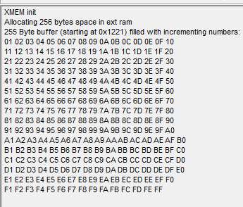
on the terminal screen we get:

In this case, heap memory is starting is at the 0x1221 location. Meaning that .data and .bss sections are between address space 0x1100 to 0x121E. You can check these locations in .map files. In my case .data section starts at 0x1100 and .bss section-starts at 0x1114. And also, I find that memory for heaps is allocated at 0x111e. So our *mem pointer points to heap memory starting with 0x121E.
Let us test another situation when external memory is used only for heaps. For this we need to change linker options like this:
-Wl,--defsym=__heap_start=0x801100,--defsym=__heap_end=0x8030ff
Then we expect our memories to be allocated this way:

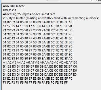
After compilation we can see the results in the terminal:

We can see that our heap is placed at the start of external memory. First, two bytes are used to hold the size of the allocated area. Let us look at the .map file.
.data 0x00800100
.bss 0x00800114
__heap_start = 0x801100
__heap_end = 0x8030ff
We can see that the .data sector is allocated at the beginning of internal RAM (0x0100), then goes the .bss sector, while the heap for the heap is dedicated to the whole external RAM.
Which memory allocation model use – it depends on your application. If you will use big data buffers for holding graphical information ready to send to displays – definitely allocate external RAM for heaps only. In another case, if you are going to use RTOS with lots of tasks, then probably it is best to leave more internal RAM for STACK and move static data to external RAM.
This is only a surface of what we’ve “scratched.” There are lots of more things you can do with memory allocations and sectors. There are some great resources, starting with AVR Libc. Good luck. Eagle and source files.


Just when I thought no one used external memory, someone comes up with a post about it.
Lovely. You could also, show a bit more about connecting other peripherals with external addressing. Ok, it takes a bit more external logic, but not having to mess around with serial comms is bliss. 🙂
Good post. Keep it coming.
Congratulations! This is exactly the extension PCB that I had in mind when I added the JP4 header for the Piconomic AB111-4 board 🙂
FYI, I published a short tutorial on exactly this topic:
http://www.piconomic.co.za/fwlib/group___a_v_r___t_u_t13___x_m_e_m.html
Please update your links in previous blogs/articles 😉
http://www.piconomic.co.za/fwlib/index.html
Also, the development board CAD files are included in the “piconomic_fwlib_0.3.0_20100813.zip” that can be downloaded from:
http://code.google.com/p/piconomic/downloads/list
Happy playing!
Pieter
Although the article suggests the limit is 64kByte, you can use other spare port pins as the high-order address bits and get even more memory space. You have to manage the paging yourself however.
64Kbyte limit is only for XMEM interface. With manual paging it can be expanded to much more.
how much more?
How you you move the #$%& ads off the web page so you can read the text?
Thankyou
This is very helpful
Sameer
Hi
This is very nice Blog i like it very much
Nice Work
AVR 8-bit Microcontroller With 128k Bytes In-system Programmable Flash datasheet from
http://www.dz863.com/datasheet-815973163-ATMEGA128_8-bit-Microcontroller-With-128k-Bytes-In-system-Programmable-Flash/
Thankyou
This is very useful for me.
i have tested the code , but the data displayed on terminal have an error every 64 byte.
the first 64 byte have a error in the data, then the next 64 byte data didn’t error.
Any suggestion please regarding my problem ?
Thank You