Eagle CAD PCB footprints for audio processors TDA7313 and TDA7315
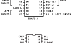
TDA7313 and TDA7315 are digital controlled audio processors used in applications where digital control of audio is needed. TDA7313 and TDA7315 are pretty the same just TDA7313 is more complex by having 3 stereo input channels and two outputs (front and rare). Both chips have volume control (step=1.25dB), tone (bass and treble) balance, independent faders for each output processor. Also, there is loudness functionality. TDA7313 and TDA7315 have low distortion and low noise, making them ideal for quality audio applications for car audio and Hi-FI systems. MCU can control both chips via the I2C(TWI) protocol. This makes it easy to interface microcontrollers with additional features like LCD, buttons. Or control directly from PC using RS232 or another interface. Both chips can be found in DIP or SO packages. Here are Eagle libraries of both digital audio processors that I have made. tda7315.zip(2kB) tda7313.zip(2kB) I have intent to make a control board with TDA7315 with LCD and button control using an Atmega8 microcontroller.