How Health IT is Helping to Improve the Lives of Patients
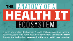
Health IT has essentially created a new ecosystem that helps improve the lives of patients while also making life easier for physicians. In the past, if a patient was sick or needed help with anything, they either had to make an appointment to see a doctor or drop in at the emergency room. Patients can now, however, take advantage of the technology available to speed up care. It is now possible for patients to receive a remote area diagnosis by receiving a consultation via video chat. Patients also have access to health wearables which can help monitor everything from heart rate to blood glucose levels. The data from these devices can be sent immediately to health care providers to ensure a patient is an inadequate health.