Microwire compared to SPI and I2C

Microwire is a three-wire serial interface used by National Semiconductor in its COPS processor family. The three signals are SI (serial input), SO (serial output), and SK (serial clock). SI and SO are input to and output from the processor, respectively. The processor clocks data to the peripheral on SO and receives data on SI. Data in both directions is captured on the rising clock edge. Peripheral devices that transfer data in only one direction (such as display drivers that are only written, never read) may implement only one data line, SO, or SI. Microwire is an older protocol than SPI, and it has some differences from it. Original Microwire has fixed clock polarity and clock phase. At the same time, SPI can be configured to any clock polarity and phase. Unlike I2C, the Microwire protocol has no device addressing built into the serial bitstream. Microwire peripherals require a separate chip select input, one per device. This allows data to be transferred more quickly since address information is not needed. However, it requires more port bits since one chip select, using one port bit, is needed per peripheral. Each Microwire peripheral has a unique protocol based on the application. The…

Continue reading

Microcontroller Simulators and emulators

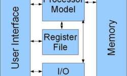
Sometimes you haven’t the ability to flash a microcontroller to test program functionality in the development phase. For this, there may be many reasons, like you don’t have a prototype ready or you need to test parts of code, and so on. For this, there are software simulators used that simulates microcontroller work without microcontroller itself. Simulators usually don’t have a connection to the real-world all operations are simulated in software. A microcontroller simulator is a program model that imitates its work. Modern simulators now simulate arithmetic operations and I/O operations and even peripherals like timers, ADC, USART, I2C, and so on. In many cases, it is possible to prepare the whole project using the simulator and then burn compiled code to a real microcontroller. Simulators usually allow: debugging at source code level; follow operation time in slow motion but with real-world values; connect stimulus signals like they are real-world signals. The simulator can be expressed as several blocks interconnected with each other:

Continue reading

Multiple controllers in one design

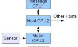
Actually, many embedded systems use multiple microcontrollers and microprocessors. This is not about multi-core processors but several distinct processors used in one design. Multiprocessor systems allow the distribution of computing power among different processors, and this way, overall speed may be increased, coding simplified, and modularity reached. Using multiprocessor embedded design has many benefits. One of them is modularity. Imagine a situation when a particular microcontroller-based subsystem needs to be installed only if a particular opinion is installed. Another, as we mentioned, is coding simplicity. Instead of writing and debugging one complex firmware, it may be broken into several distinct, easily manageable functions on different MCU’s.

Continue reading

Debugging embedded hardware and software traces

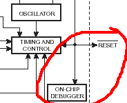
When designing an embedded project, we typically focus on the actual application but do not pay enough attention to the hardware and software debugging process. Adding the debugging capability to the project requires some strategy. Simple situation: hardware may not be installed but connected to another circuit when needed. So software must support the functionality regardless of whether or not hardware is installed. Another example may be Embedded inboard with multiple temperature sensors. Hardware should detect when the sensor is connected or disconnected without interrupt other sensors’ readings. One way of debugging is software trace(log) to provide historical information on what was happening if something went wrong. This technique is a good solution for developers who have no ability to use other debugging tools because of the following reasons:

Continue reading

Understanding and conversion different firmware file formats

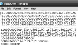
Without getting too deep in discussions about why there are several firmware formats and extensions used. But the fact is that you can face firmware files with extensions like BIN, HEX, or E2P. Let’s see how these files look like and how to convert between them. First of all, it is important to mention that all firmware files can be one of two types: Text files contain ASCII symbols (codes from 32h to FFh); Binary files contain all ASCII symbols including nonprintable symbols (00h to FFh). First advice – never rely on file extension as it can be any. All are inside the file. So how to define what’s inside the file and what format? One easy way is to open a file with a notepad and see how the contents 犀利士 look inside. Continue reading

Continue reading

Compact dual oscillator and power on reset for MCU

Would you consider connecting an IC with a dual-speed oscillator and a power-on reset to your MCU? This is what MAX7378 does. This is a good replacement for ceramic resonators, crystals, and other oscillator modules, and discrete reset circuits. The good thing here is that at any time, you can select either low-frequency 32.768kHz or a high frequency from range 600kHz to 10MHz.The clock frequency can be switched at any time without glitches. MAX7378 can be powered from 2,7V to 5,5V, so it is suitable for most MCU types. Comparing to Crystal resonators, it is resistive to vibrations and EMI. It is a good solution for the automotive and industrial environment. High-frequency oscillator error reaches ±2% at 25°C at 5V power supply. In other words, speaking oscillator frequency stability is about ±325ppm (when crystal stability is from ±10ppm to ±100ppm). So it doesn’t correspond to crystal accuracy, but it suits most non-time-critical applications. 32.768kHz oscillator is more accurate with an error of 1%, but it still a bit much for time measurements.

Continue reading

IR remote control signal receiver using AVR microcontroller

IR remote control is a device you can find everywhere to find a TV, VCR, or home theatre. Why not use one of them for controlling your own devices like light, air conditioning, etc. As we know, remote control devices use IR light. This is invisible light of about 950nm wavelength. One most significant problem in using IR light is that there many other sources of it like the sun, light bulbs, fire. To exclude other sources, the IR signal is modulated by some frequency. The receiver has to be tuned for this frequency. Mostly remote controls transmit IR signals using 36kHz frequency signals. Transmitting and coding is one part that can be done more efficiently than receiving and decoding. Decoding is usually performed by using microcontrollers. First of all, the receiver has to get rid of the 36kHz carrier frequency. This is not a simple task to demodulate the signal; this is why particular IR receiver IC’s are produced. One of them is TSOP1736:

Continue reading

Generate true random numbers on microcontroller

Sometimes there is really a problem of how to generate truly random numbers using your microcontroller. Usually, a computer processor or any other MCU can generate a Pseudo-Random Number (PRN). These numbers are generated by algorithms, so-called Pseudo-Random Number Generators (PRNG). Everything that a pure algorithm produces is predictable at some level. Many PRNG algorithms generate random numbers, but there is always a defined number of iterations when a random number sequence will repeat itself. Sometimes it may be acceptable. One popular way to generate pseudo-random numbers is using Timers. The universal algorithm is the concept of the Linear Feedback Shift Register (LFSR). LSFR is an n -bit register initiated with a non-zero seed value and is clocked by shifting values to the left and loading a new bit into bit0. The new bit is calculated by XORing the bits of selected taps of LSFR. This method is used in rand() functions.

Continue reading

Neural networks and artificial intelligence in robotics

When talking about artificial intelligence(AI), many people think that neural nets should be as intelligent as the human brain. Some people don’t even imagine how widely they are used in their life. Let’s narrow us to something more simple and understandable. The most exciting usage of AI is robotics. Today isn’t tough to build a simple robot with a few sensors and a couple of motors. But the harder part is to make it react to the real-world as you expect it to be. When programming the robot brain, there is checking sensor states and reacting to particular circumstances like hitting the wall, line on the ground, etc. But more sensors robot has more complex reactions may be. Programming of more complex systems may be painful without using simple neural networks.

Continue reading

High capacity multimedia cards in embedded systems

Multimedia cards are popular around us. There are well known Compact Flash, CD, MMC Memory Stick. Usually, when you make a new design with external memory, you consider EEPROM or Flash ICs with some capacities with up to a few Mb. But why limit yourself? Because in some cases, it is smarter to add a multimedia card socket and use any capacity (even a few Gb) multimedia cards in your projects. Using removable storage cards you get few advantages: You can share data from your card with any device that has a reader; You can have any size of storage memory; Easier to get one than specific IC; Cost-effective; I really like Using multimedia cards because you can get huge amounts of storage of price small EEPROM or Flash IC. They are cheap because of mass production. They are available everywhere: digital cameras, Mobile phones, personal players, etc. Another advantage is that you can store data in a format that the PC understands. This way, it is easy to collect data for later analysis using PC software.

Continue reading