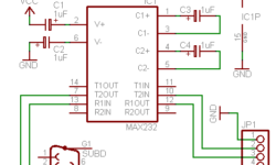
RS-485 interface for connecting multiple devices

RS-485 is an updated version of the RS-422 interface. It is designed to communicate between multiple devices connected to a single data line. Standard allows connecting 32 transceivers to the data line. This is achieved by using tri-stable drivers that are separately programmable. This allows only one device to work at a given time. Resistors used in the circuit are so-called termination resistors for matching the transmitter and receiver impedances to avoid reflections. The matching resistor depends on the cable used but is 120Ohm.

Continue reading

RS-422 interface basics

RS-422 is a standard for serial data transfer similar to RS-232, but it uses the difference between two lines (RS-232 uses a reference to ground). RS-422 uses twisted pair (difference pair) to represent the logic level. Such data transmission type is so-called balanced transmission as it is not referenced to ground. This is a noise-proof solution because the same noise affects both lines, which are differentiated out. This allows carrying data at much longer distances at higher data transfer rates. RS-422 can transmit data to up to 1200metters. The maximum transfer rate can be 10Mbits/s. 120Ohm resistor acts as a terminal resistor that removes reflections, that may occur during transmission over long distances. Voltage levels between twisted pair lines are 4V and between transmission lines is 12V. RS-422 can be compatible with the RS-232 interface by simply connecting the negative wire of the twisted pairs to the ground.

Continue reading

Dealing with switch bounce problem

Normally any embedded system has relations with the real world. The simplest and most common way is using buttons. This is how applications interact with humans. But real-world like a human is not perfect. Practically mechanical contacts bounce (turns on and off repeatedly for a short period). And you cannot do anything about it. There is no need to look for higher quality buttons or try special button construction or even try to press the button precisely for simple applications. It is better to deal with it wisely. In digital circuits, there may be used special circuits like triggers, RC circuits, etc. But when working with microcontrollers, there is simpler to remove bouncing by adding a couple of code lines. Usually, switches bounce for less than 20ms; bigger ones may take up to 50ms.

Continue reading

Use neural sensors to build smart sensor systems using microcontrollers

Neural networks are a broad topic. But this small example demonstrates how to create a primary neural sensor that takes resistive readings from multiple sensors and multiply it by weight factor and then sum the results. Results are compared to a three-level threshold. Without going too deep into neural networks, we can say that neural cell thresholds are similar to natural biological neurons. For instance, pain levels: itch is a low pain level while burning sensations are combined with cold and warm feelings. Neural sensors can operate in the same way. Let’s take typical neural sensors, which consist of two inputs with some weights and three outputs. Depending on the threshold level that the sum of inputs gives – we have an output signal on three outputs.

Continue reading

Function calls and stacking of parameters in embedded systems

Usually, when you write C programs for microcontrollers, you use functions that can be called any time in the main program or another function. The compiler compiles these functions as subroutines. These functions can be called from the main function or other functions – this is called nesting (nested subroutines). If you see the compiled program’s listings, you will see that subroutines are called by using the call or rcall keyword. The argument of this instruction is a subroutine address that will be executed on the next processor cycle. Call instruction also writes return address from function to the stack to continue the program after returning from the function.

Continue reading

Simple TTL to RS232 adapter

During my spare time, I made a quick TTL design for an RS232 adapter that works with my AVR development board. This adapter helps to connect TTL (Transistor-Transistor Logic) level signals to the RS232 interface. TTL side is a 9-pin female connector, and RS232 sire is a male connector. The unit is powered from the target board using power pins. The RS232 TTL adapter circuit: Put all the in a plastic case and see what I have got:

Continue reading

All you need to start with Atmel AT89 microcontrollers

This is a simple development board for the Atmel AT89 series of microcontrollers that uses ISP programmability I found in sixca.com. This is a good start for learning with MCS-51 based projects. This board supports Atmel microcontroller series like AT89S51, AT89S52, AT89S53, AT89S8252 with DIP40 pin packages. The board uses the ISP programming method through the parallel port adapter. It has all I/O connectors, single-sided PCB. It has an onboard voltage regulator 7805.

Continue reading

Interfacing LCD display to 3V circuits

Usually, we are used to connecting LCDs to 5V systems. LCD controllers usually require a 5V power supply, and there must be some compliant circuitry used when interfacing to 3V systems like ARM LPC2000 microcontrollers. Here are few examples how this problem could be solved. Solution number 1 Standard LCD microcontroller can work with lowered power supply voltage to 2.7V. For this negative voltage for regulating contrast is needed. For this special inverting IC is needed or another solution. In this case, there is the ability to write and read from the LCD controller.

Continue reading

Interface multiple keys with one wire and save pins of MCU

Usually, the keyboard is connected by using matrix type of connection – rows and columns. For instance, for a 12 button keyboard wee need 3+4 digital inputs of the microcontroller. There is a way to build a keyboard and connect it to the microcontroller using only one wire. For this, we will need only signal wire, power, and ground, and of course microcontroller must have analog ADC input. One wire keypad circuit: The circuit is nothing more than simples digital to analog converter. The microcontroller reads the voltage from the signal line and calculates which key is pressed. Let’s see how it works. If no keys have been pressed, then the line has a voltage equal to a power source. If any key is pressed, the voltage divider divides the voltage according to the resistor connected to this button. A capacitor works as a filter of mechanical noise during button contact. This way microcontroller can check the voltage of the signal line and calculate which button is pressed.

Continue reading

Programmable logic devices

In a market, you can find a bunch of programmable logic devices – PLD. They can be small scale integrated – SSI, medium-scale integrated- MSI, mask programmed gate array – MPGA (MPGD – masked programmable logic devices). Now the most popular are FPGA (Field Programmable Gate Arrays). What is the difference between FPGA and MPGA? MPGA is hard-coded during manufacturing and cannot be erased or reprogrammed, while FPGA is programmable – usually EEPROM or SDRAM. Of course, there are other differences between FPGA and MPGA. One of them is speed. MPGA usually is faster as MPGA needs fewer elements to form a logic gate while FPGA needs additional elements to enable programmability – this adds additional resistances and capacitances in circuits. But today’s technology allows reaching significant speeds with FPGAs too.

Continue reading