
Microwire is a three-wire serial interface used by National Semiconductor in its COPS processor family. The three signals are SI (serial input), SO (serial output), and SK (serial clock). SI and SO are input to and output from the processor, respectively. The processor clocks data to the peripheral on SO and receives data on SI. Data in both directions is captured on the rising clock edge. Peripheral devices that transfer data in only one direction (such as display drivers that are only written, never read) may implement only one data line, SO, or SI.
Microwire is an older protocol than SPI, and it has some differences from it. Original Microwire has fixed clock polarity and clock phase. At the same time, SPI can be configured to any clock polarity and phase.
Unlike I2C, the Microwire protocol has no device addressing built into the serial bitstream. Microwire peripherals require a separate chip select input, one per device. This allows data to be transferred more quickly since address information is not needed. However, it requires more port bits since one chip select, using one port bit, is needed per peripheral. Each Microwire peripheral has a unique protocol based on the application. The number of bits and the meaning of each bit varies. For example, National’s Microwire EEPROMs have a 4bit command followed by an address (7 to 12 bits, depending on memory size), followed by data (8 or 16 bits). The commands are erased, read, program, enable programming, and so on.
Microwire can transfer data faster than the original I2C, typically at MHz rates. The SPI bus, used by Motorola on its 68HC11 family, is similar to Microwire, and many peripheral ICs are specified as being compatible with either.
Both SPI and Microwire are implemented in their respective processors with hardware, which simplifies programming. However, peripherals using these buses can be interfaced to any general-purpose microcontroller using software-controlled I/O. Generally, the same peripherals available with the 1% interface are also available with SPI or Microwire.
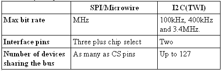
A summary comparison between SPI/ Microwire and I2C
Note that many Microwire devices have both data-in and data-out pins. In some cases, clocking data into a Microwire device will also clock data out of the output pin. You must read the output bit on those devices after each bit is clocked into the device; otherwise, the output bit will be lost. The Maxim MAX3100 UART is a typical example.
Also, note that many SPI/Microwire devices perform operations, such as latching previously written data, on the rising edge of -CS. Consequently, the -CS signal must remain stable throughout the access cycle.
Of course, all three interfaces have the advantage of being tolerant to large oscillator variations, as all data transfers are synchronized to the master’s shift clock. SPI and Microwire give speed, but they are effective as single master and single slave applications. At the same time, I2C can connect multiple slaves to a single master because of addressing.
References:
- Embedded Microprocessor Systems: Real World Design Stuart R. Ball P.E., 2002;
- https://www.ucpros.com/