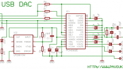
Modeling of analog part for DDS3 signal generator

When building an AVR DDS2 signal generator, there were many discussions about signal conditioning in the analog part of the device. The first argument was that LM358 wasn’t the best choice for this purpose. Another one pointed to the sine wave that wasn’t smooth enough. As you can see, there are some dents on it. Other waveforms also are distorted, especially when higher voltages are selected. This asks for a better analog part. Some people suggested replacing LM358 with OPA2134, but it seems to be quite an expensive choice. In my opinion, low noise, a general-purpose op-amp can be great too. I’m going to give a try to Texas Instruments TL074 low noise op-amp. It is low power, high slew rate (13V/us) IC – almost five times faster than LM358 and for the same reasonable price.

Continue reading

Multivibrator – back to basics

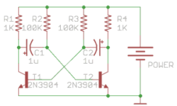
Multivibrator circuit is one of the first projects you start learning electronics. It is a beautiful circuit widely used for educational purposes and even in end projects as waveform generators. Lots of hobbyists grab a microcontroller/Arduino to blink LEDs. But using basic circuits like multivibrator may be cheaper, faster, and even fun. [Ray] decided to go through multivibrator theory and explain its working in detail step by step. The circuit itself consists of two transistors, two capacitors, and four resistors. When powered, the circuit generates a square wave signal that can be used to flash LEDs or clock other circuits. You will get an intuition on what causes multivibrator to develop generate. Formulas allow calculating resistor and capacitor values for a particular frequency. If you are a starter in electronics, build one on a breadboard and do some experiments, why not start with Christmas lights.

Continue reading

Does Electronics Really Help Us

Electronics is a vast stream. The subject is pervasive in itself. Electronics are the primary source of almost everything that is happening today. The whole working of the items is dependent mainly on the electronics base. In our daily lives, we can see uncountable examples of the number of electronics used around us. From our environment itself, we can see how electronics can find their use in so many work departments. Human beings are slowly becoming addicted to the use of electronics in their lives. They have become almost dependant on the machines for their work. For example, the computer is the most commonly used machine, which is the best illustration of electronics in our lives. People have started being dependent on these machines to a large extent. All the work that was earlier known to be done by the people is now seen as to be done by the various devices and also the computer. Such is the help provided by the electronics to the people in their lives.

Continue reading

The Great PLL Induction Heater Driver

Have you ever played with a manually tuned induction heater before? If you did, then you must know that how dull it could be… Oh, for those that didn’t know what the induction heater is, that is a key piece of equipment used in all forms of induction heating. An induction heater will technically operate at either medium frequency (MF) or radiofrequency (RF) ranges. Three main components form the basis of a modern induction heater, such as the power unit (power inverter), the word head (transformer), and the coil (inductor). This project is slightly different from the regular induction heater driver, as it will include the Phase Lock Loop (PLL) into it. A phase lock loop is a control system that can generate a signal, and it has a fixed relation to the phase of a “reference” signal itself. Since the phase lock loop circuit responds to both the frequency and the input signals phase, it raises or lowers the frequency of a controlled oscillator automatically until it’s matched to the reference in both frequency and phase. Overall, this PLL induction heater driver will be one of the magnificent projects that you’ve ever built!

Continue reading

Circuit Diagram

A circuit diagram is also known as an electrical diagram, wiring diagram, elementary diagram, or electronic schematic. It is a simplified conventional symbolic representation of an electrical circuit. It shows the circuit components using easily understood symbols and the power and signal connections between the devices. The components’ arrangement and their interconnections on the diagram do not correspond to their physical locations in the finished device. Unlike a block diagram or layout diagram, a circuit diagram shows the actual wire connections being used. The chart does not in any way represent the physical arrangement of components. Circuit diagrams are used for the design, construction, and maintenance of electrical and electronic equipment.

Continue reading

Analog Circuit Design

constant_current_LED_driver_circuit

Today’s modern circuit design is a bit of a conglomerate thanks to the availability of sophisticated process technologies that have made bipolar and CMOS (Complementary Metal Oxide Semiconductor), power and signal, passive and active components available, all on the same die. From this point on, it is up to the circuit designer’s ingenuity to assemble these components into the analog and/or logic building blocks that are deemed necessary to develop the intended system on a chip.

Continue reading

Radio Frequency Identification

Radiofrequency identification (RFID) is an identification system that uses radio waves to send data and RFID tags or transponders. The first patented RFID device was a passive radio transponder with an integrated memory by Mario Cardullo. At present, the technology has many applications, particularly in the retail industry because of its small size, low power demands, and high levels of efficiency offered. The application of RFID is seen as the next generation of barcode technology currently in use.

Continue reading

What are MEMS

Today MEMS is a common acronym among engineers. Therm MEMS stood for micro-electro-mechanical system and was started to use in 1980sin USA. MEMS are called systems because they are sensors and contain electronic circuitry inside which conditions sensor signal. Simply speaking, MEMS is usually a chip device that integrates mechanical elements, sensors, actuators, and electronics. Most interesting and important partis mechanical. Miniaturizing the mechanical parts using micro-machining technology when selectively parts are etched away, it became possible to create mechanical structures on silicon base and electronic devices. MEMS devices are used everywhere today, including automotive, industrial even computer hard drives with MEMS sensors for shock protection. The ability to integrate mechanical sensors inside the chip made it possible to design compact accelerometers, gyroscopes, pressure sensors, sensors with integrated RF, and many more. Also, technology enables the integration of more than one sensor inside the chip. One example may be 3-axis accelerometers. A major producer of inertial MEMS is Analog Devices, which produce accelerometers and gyroscopes.

Continue reading

Quality music sound in the car

Most of the driver’s car is more than a vehicle. Sometimes people spend hours in the car every day and listens to the news radio broadcast and listens to music. Having good quality music sound in the car requires more than good speakers and power amps, but some smart solutions are also needed to make it sound better. There are plenty of publications on how to DIY a good car sound system at home in the current time. Even the best power amplifier does not guarantee that car music will sound like Hi-Fi class. The main problem is the hard installation of the audio-system inside the vehicle. In many cases, speakers are installed where ever they fit in the car. But there is also no clear answer where it is the best place to install speakers and how. The most common mistake is to place powerful high-quality speakers in the rear shelf while the speaker’s front position is installed or not at all. Such an audio system installation gives a feeling like he is sitting back to the scene.

Continue reading